The pins in Port 1 has internal pull-ups when used for input. The Mosfet is off and the drain is pulled high using an internal pull-up resister.
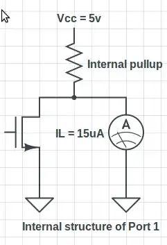
I connect an ammeter and see that the current (IL current) flowing to ground is about 15uA. I inferred that the value of the internal pull-up resister is 333k.
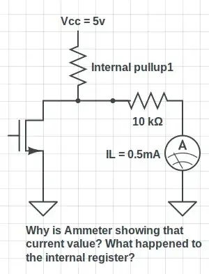
Now I connect a 10k resister and measure the current. I get 0.5mA (5/10k). What happened to the internal pull-up resister? Is not the internal pull-up resister and the 10k resister in series?
What is happening? When I use external pull-up at Port 0, things appear as expected - Resisters in series and both resisters acting as voltage divider to create a voltage drop at the pin.
ps: I am using AT89s52.
ps: The same problem exists in port 2,3
ps: Here is the current for different resisters:
- 330 ohms - 15uA
- 1k - 15uA
- 100k - 50uA
- 220k - 22uA
The Max IL (as per datasheet) is -50uA