Firstly, what doesn't make this antenna better than others?
The shield does not block electric fields while passing magnetic fields. For AC magnetic fields, this is impossible.
This antenna, or any electrically small loop, does have a low field impedance in the very near field, meaning the ratio of magnetic field to electric field will be high. This is in contrast to a short dipole, which is the opposite. But farther away, but still in the near field, the field impedance of a loop antenna is actually higher than that of a short dipole. In the far field, they are identical. So, it could be that some near-field noise sources are picked up less by a loop than some other dipole, but it's hard to predict. Changes are most likely due to luck than anything else.
What makes small loop antennas in general useful in noisy environments is that there are two very deep nulls in the radiation pattern, each perpendicular to the plane of the loop. Noise sources can then be nulled very effectively.
The shield does not change the pattern of the small loop antenna directly. If one takes a conductor, bends it in a hoop with a small gap, and measures the signal across the gap, this ideal pattern with deep nulls is the result. The problem is this is really hard to do in practice. The feedline, unless exactly symmetrical, will unbalance the antenna. The feedline then acts like a vertical antenna, and the radiation pattern is a combination of the ideal small loop and a vertical. You don't get the deep nulls.
It's really hard in practice to assure symmetry. Coax is not an option, as it's not symmetrical. The ground and nearby objects can disturb the balance.
Wrapping the antenna in a "shield" is a clever trick to make it more practical to construct a balanced antenna. The shield isn't actually a shield -- it is the antenna. The gap in the shield is the feedpoint. Currents circulating in the loop are our signal of interest, and those currents create a voltage difference at the gap. At this point, we have our ideal small loop antenna, but we don't have anything connected to the feedpoint, so it's not useful.
By running a conductor in a loop inside this shield, the voltage difference at the gap can induce a current in that conductor. But we need the wires to exit, somehow. And we probably want them to exit inside a shield (ie, coax), otherwise we haven't solved anything because anything near the feedline will further unbalance it. The only place a shield can exit is opposite the gap, because any other point would be unbalanced. Here's the result:
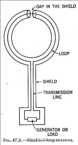
This is from Transmission Lines, Antennas, and Waveguides, which is no longer protected by copyright.
Now the gap is the feedpoint, the shield is the antenna, and the antenna (the shield) is symmetrical with respect to ground. Our feedline is also shielded, and we have a robust, balanced antenna which can deliver close to the ideal small loop pattern in practical environments.