There are multiple ways of doing it. I will explain one design that's very cost effective and quite ingenious. It's the design of LinnStrument. You can have a look at its sensor board. Since I didn't do the sensor design, nor do I own a LinnStrument, the below is all a result of reverse-engineering and may not match the original design. Certainly the mechanical and material choices don't.
TL;DR: It's possible to scan a LinnStrument sensor plane using nothing but MCU pins and a resistor per column. No external op-amps nor multiplexers are needed.
Mechanical
The sensor board uses a piezoresistive material such as Velostat. Such material decreases its bulk resistance with increasing pressure. The strips of the material are laid in a grid, and scanned to measure the pressure and position within each cell. I'll elaborate on that below.
A prototype design might look as follows, going top-to-bottom:
- adhesive plastic foil cover (large adhesive sheet),
- column strips,
- double-sided adhesive sheet with large holes cut out at each row-column intersection, to provide an air-gap between rows and columns,
- row strips,
- a non-conductive base plate (say an acrylic sheet) covered with double-sided adhesive. The base plate should offer a 1/2-3/4 inch margin around the grid, so that the terminations can be properly retained without stressing the rows and columns.
A sheet of thin silicone can be installed on top of this sensor assembly, for a softer feel.
The intersection of each row and column is called a cell.
When assembling, it's fairly important that the columns stick well to the top foil cover, and that the rows stick well to the base plate. This ensures that the air gap will not be prematurely bridged. Thus you should assemble (1)+(2) and (4)+(5) separately, then install the (3) on either one, and then sandwich it up.
If you wish the cells to feel springy and somewhat "weird", you can leave the air-gap enclosed, with air trapped inside. Alternatively, you can cut a small central hole through each cell in the (4)+(5) assembly, prior to sandwiching it with the rest of the sensor. This vents the air gap and offers a different feel.
A half inch on either end of each row and column strip should protrude from this sandwich. Copper tape with conductive adhesive is used to get connections to the ends of each row and column strip. Make sure that you solder connecting wires to the copper tape before you attach them to Velostat. Velostat has very low melting point. You will ruin your painstakingly assembled sensor assembly if you forget that (yeah, I know from first-hand experience).
When mounting the row- and column-strips, it's important to slightly pretension them, so that they are perfectly flat when applied to the adhesives.
As far as I can tell, that's more-or-less Roger Linn's design, inasmuch as the sensor board's picture and the firmware can be used for reference.
With ample experimentation, you should be able to get to cut the Velostat strips using Cricut, while already laminated to either the cover or the base plate. After cutting, you can peel off the thin isolation strips between the rows/columns. This would be useful if you wanted to have a more accurate sensor without swearing each time a column or row stuck down to the adhesive before you got it properly positioned :)
Limitations
When you actuate four corners of any rectangle on the sensor plane, you short two rows and two columns, and thus effectively take them offline and unusable for other measurements.
To overcome this limitation would require to inter-row pick-offs (connection points) on every column, not only at the ends of each column. For a 4 row matrix, you'd need 5 connections on each column - on each end, and between each row. This would complicate the design.
References
A basic, single-cell design for Z-axis sensing can be seen here. Since it has a single Velostat square without separate row/column pick-offs, it can't sense the pressure position. A simple modification to this FSR would be to attach narrow column pick-offs along the Top/Bottom edges on the front face, and along the Left/Right edges on the back face. It'd allow read-out of X, Y and Z values.
Scanning
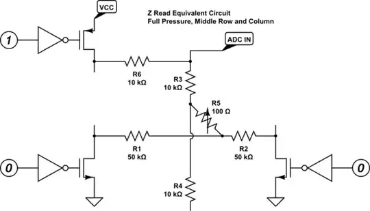
Z (pressure) detection
- Both ends of one row are grounded.
- Both ends of one column are attached to the same A/D channel input and a pull-up (divider) resistor. The resistor forms the upper half of a voltage divider, the bottom half is the pressure-sensitive resistance between the row and the column. The sensitivity of each grid position is different, so there needs to be a per-position multiplier applied to normalize the reading.
Once you've detected a touch within a cell, you can do more: you can detect the position of the press within the cell. Thus you can do pitch bending and texture modulation.
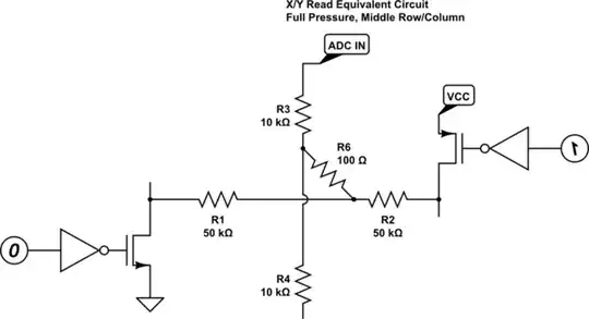
X position within the cell
- The ends of one row are connected to 0V and VCC, forming a position-to-voltage converter.
- Both ends of one column are connected to the same A/D channel.
Y position with the cell
- The ends of one column are connected to 0V and VCC, forming a position-to-voltage converter.
- Both ends of one row are connected to the same A/D channel.
How to do it on the cheap?
The sensor surface itself can be assembled for under $100 in materials, much less if you aim for a small surface. The most important tools that you'll need are an X-acto knife with sharp blades for it, and a steel ruler to cut the materials. Some experimentation on a single cell is necessary to evaluate the particular materials used.
An ingenious way of scanning such grid without need for any signal conditioning is given below. This is a simplification over the original design, which uses analog switches and some signal conditioning. It still performs adequately and has the advantage of requiring no components external to the MCU, save for a few resistors. The assumption is that rows are physically no shorter than columns - this helps with the accuracy of Z sensing. You can of course play it in any orientation you wish.
All we need to interface to the sensor surface are the GPIO pins: no external switches needed!
The sensor performs adequately even if you connect the A/D channel to only one end of a row or column, and leave the other end floating. This allows us to use the pin multiplexer functionality present in most any MCU with analog inputs.
The sensing of one cell operates as follows, with all other pins set as inputs:
- Z: both ends of the row to 0V; one end of the column to A/D and pull-up.
- X: one end of the row to 0V, another end to VCC; one end of the column to A/D.
- Y: one end of the column to 0V, another end to VCC; one end of the row to A/D.
Suppose we have a 4x4 grid and 8+8+4 GPIO pins, 8 of which can perform A/D conversion. The sensor grid has 16 direct connections to GPIO: two ends of each of 4 rows and columns. Let's label the ends of rows as 0L, 0R through 3L, 3R, for left and right ends of rows 0 through 3 respectively. Let's label the ends of columns as 0T, 0B through 3T, 3B, for top and bottom ends of columns 0 through 3, respectively.
- The rL and cT ends go to GPIO pins that can double as A/D inputs.
- The rR and cB ends go to regular GPIO pins.
- Each cT is connected via a pull-up resistor to another GPIO pin, we can call those pins cD.
The sensing of a cell with given row and column is then achieved by simple reconfiguring of GPIOs. The trick is to realize that any GPIO configured as input is effectively disconnected.
Z
- rL and rR set as output, driven to 0.
- cB set as input.
- cT set as A/D input.
- cD set as output and driven to 1. This connects the top half of the voltage divider to the cell.
- All others set as inputs.
- The A/D value is proportional to Z force, with different scale for each cell.
- Once a given cell is classified as "touched", you can then also obtains its X and Y value.
X
- rL set as output, driven to 0.
- rR set as output, driven to 1.
- cB set as input.
- cT set as A/D input.
- All others set as inputs.
- The A/D value is proportional to the X position.
Y
- cB set as output, driven to 0.
- cT set as output, driven to 1.
- rL set as input.
- rR set as A/D input.
- All others set as inputs.
- The A/D value is proportional to the Y position.
There is some logic involved in tracking a touch as it moves between cells, but this can be ignored if the sensor is designed with wide large cells - say 1x1 inch.
All GPIO pins should be configured for high-current drive mode, to lower their impedance and improve the sensitivity.
simulate this circuit – Schematic created using CircuitLab
simulate this circuit
In Closing
As you can tell, I've decided to make one for myself for less than $1.5k sticker price, and have some fun while doing it :)
If your student wished to leverage LinnStrument's open-source firmware with minimal changes, then the design could be based on Arduino Due, with some external analog switches and an external 12-bit A/D converter. The original design uses ADS7883, but it's a simple change to just one function to use another converter. The source code should be portable to most any platform with a C++ compiler, as long as it's fast enough.