3

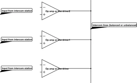
Party-line or full-duplex intercoms allow for the simultaneous transmission and reception of audio from all connected stations, i.e. effectively there is an audio 'bus' and each station takes a feed from it and routes this to its headset, and also adds a signal from its microphone that is then available to the other stations. The connecting wire can be either balanced or unbalanced.

schematic

simulate this circuit – Schematic created using CircuitLab

My question is: how do you add these signals together? Do you simply connect the outputs of the output op amps at each station together onto the wire (via some form of AC coupling, perhaps?).

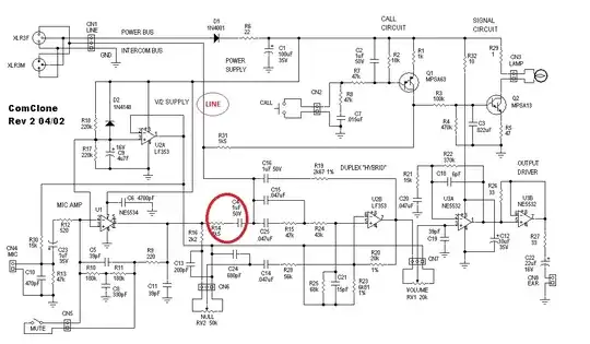
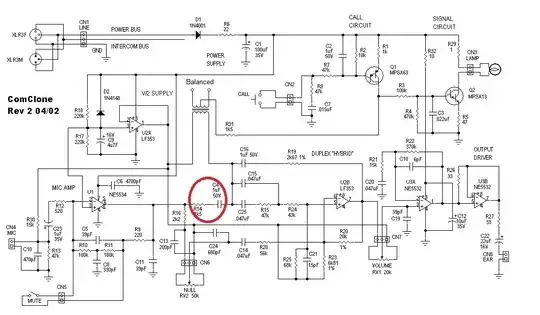
Is that what this guy does in this circuit here?: ComClone2 Circuit Diagram

PeterJ
  • 17,131
  • 37
  • 56
  • 91
John
  • 329
  • 5
  • 12

1 Answers1

2

No, that's not what he does. He feeds each microphone through an amplifier then through an output impedance that feeds the line through R14 and C4 shown in thick red circle below: -

enter image description here

I've shown the wire that is the actual line used by the intercom in a thin red/brown circle.

Because of the output impedances of several units connected all at once there will be no clash of signals and, within reason, the line voltage will be an approximate sum of the contributions of all active intercoms.

AC coupling via C4 is needed for the op-amps but note that there is a call circuit that needs to put DC onto the line to "ring" the other intercoms.

Side-tone cancellation takes place around U2B and for a 1-to-1 call you won't get feedback in your ear of your own voice. With several of these units connecting at once you may get feedback from mic to ear and this could cause havoc to other users too. So be aware of this.

Balanced Line out with DC signalling: -

enter image description here

Andy aka
  • 434,556
  • 28
  • 351
  • 777
  • So if I understand you correctly, the R acts in concert with all of the other stations on the line and creates a 'passive averager', such as the one shown here: [Passive Averager](http://www.allaboutcircuits.com/vol_3/chpt_8/8.html). C4 is just for AC coupling. This is a circuit that uses unbalanced lines - how would the coupling vary if balanced lines were being used? Would you take the mic output & put it through a line driver and then couple each differential output to the corresponding balanced line via a similar R? How do you choose the value of R? – John May 22 '13 at 10:25
  • For a balanced line, I'd use an audio transformer - the design has to work "balanced" for speech IN as well as speech OUT and the transformer offers the simplest solution BUT it will need a cap in series with its output to prevent the DC signalling getting screwed-up. Yeah, a passive averager is a good name. – Andy aka May 22 '13 at 10:48
  • Thanks (again!), but I'm not sure how the transformer would be connected. So, in general, the signal from a mic would go to the transformer and that would generate balanced output? Where do you take the feed for the speech in? Is it just across the same windings as the mic input is connected? – John May 22 '13 at 12:09
  • Ignoring the DC signalling thru R31, the transformer would be connected to where "line" is shown on the circuit. Where the small brown circle is, it has the track broken at the point. One transformer winding goes to the C4 end of the break and the output of U2A. The other winding of the transformer is the balanced output to external devices. Note that DC signalling (via R31) will no longer work because the line is coupled to the outside world via the transformer and it isolates. – Andy aka May 22 '13 at 12:30
  • OK, so conceptually speaking, [the circuit looks a bit like this](http://s14.postimg.org/xr374d6dt/Capture.png) (apologies for the rough & ready schematic)? The op amp U1.2 would be replaced by a hybrid, similar to that shown in the original diagram, if the user wishes to listen to only the received audio (rather than mic + receive, as is shown here). – John May 22 '13 at 13:44
  • I'm getting a 504 timeout gateway error thing on the link – Andy aka May 22 '13 at 14:10
  • Not sure why that should give a 504, sorry, I've loaded it up to another site: http://oi44.tinypic.com/2a82gkh.jpg – John May 22 '13 at 14:21
  • I've added it to the bottom of my original answer – Andy aka May 22 '13 at 14:22
  • So the coupling to U2A is to effectively 'bias' the transformer to Vcc/2, allowing it to swing Vcc to Gnd as the output of the mic and U2B sum together? With regards the circuit I drew, would the same thing be achieved by biasing the op amp U1.1 to half Vcc, or alternatively connecting transformer T1 to Vcc/2, instead of Gnd as shown? (I'm trying to break this circuit down into its most simplest building blocks). – John May 22 '13 at 15:14
  • It could, just as easily connect to internal GND but all the audio within the intercom are referenced to Vcc/2 so best follow the lead on this. Capacitors on the other lines prevent any DC problems caused by the transformer having low resistance coils. On your circuit GND is fine providing that is half-way between plus and minus power rails. – Andy aka May 22 '13 at 16:24
  • Also remember (though it isn't necessary for "press-to-speak, release-to-listen systems) that there are a bunch of "sidetone" components that effectively reduce what is being transmitted from the mike getting onto the earpiece thus you won't get feedback when speaking and listening simultaneously. – Andy aka May 22 '13 at 16:28