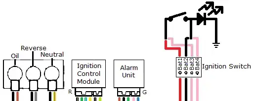
I have no knowledge about the LED, other than it's part of a switch rated for 20A @ 12VDC.
There's your problem.
Since you don't know anything about the LED, you'll need a variety of resistors (or an adjustable multi-turn potentiometer) and will have to experimentally establish what looks good to you.
Assume the LED will have a forward drop of around 1V (could be less, could be more). Start with 1mA of forward current and go from there.
\$ I_{LED} = \dfrac{12V - 1V}{1mA} = 11 k \Omega \$
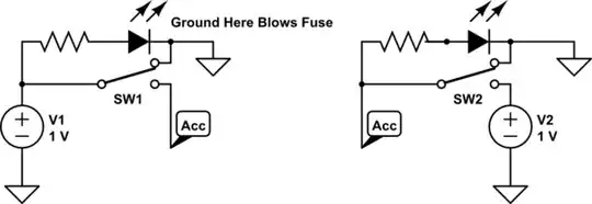
Then, install the resistor in series with the LED, apply power, and measure the battery voltage and the resistor voltage to actually figure out the LED voltage drop and power:
\$ V_{LED} = V_{BAT} - V_R \$
\$ I_{LED} = \dfrac{V_R}{I_R} \$
\$ P_{LED} = V_{LED} \cdot I_R \$
\$ P_R = V_R \cdot I_R \$
Repeat this iteration of increasing the LED current / reducing the resistor value until you find the minimum LED current that's useable for you (i.e. bright enough to see) and go with it. Also make sure your resistor is sized appropriately. (Using a fixed resistor once you settle on a value will be more reliable then leaving a potentiometer in the circuit.)
If you arbitrarily go with too much LED current, the LED will end up with a short lifespan and go dark prematurely.