I have a project I'm working on that will have an Arduino running on 2 or 4 rechargeable NiMH AA batteries. I say 2 because I might boost up the voltage to what's needed. My problem is that this project will sometimes be plugged in and I would like the batteries to be able to charge during that time. These batteries will each have a capacity of around 2000-2400 mAh.
I must have done half a days amount of research on this topic and although I feel much more informed I still don't know how to proceed. Based on what I've read the most important thing is a constant current, with < .1c trickle charge for NiMH batteries and ~2c 1.2cSource linked below for a fast charge.
First off, is there a way to make a crude 'dumb' charger with say an external 12v power supply and the Arduino reading the battery voltage and shut off accordingly? If so where should the voltage be read at along the circuit for it to properly read.
I'd like to know that last bit the most, because regardless of what charging mechanism in the end is selected, I wish to know whether the Arduino can read the battery voltage while the batteries are plugged in.
Also, should I in the end use an IC like http://www.digikey.com/product-detail/en/BQ2002PN/296-9326-5-ND/379871 and let it take care of the entire situation. If so is the one I have selected a good one for this particular application?
Edit
I have tried to continue research and attempt to present a circuit. I will say this is the most complicated circuit I have attempted to design. Besides the couple dozen schematics I had looked at, I mostly used the following:
http://www.ti.com/lit/ds/symlink/lm317l.pdf
http://www.learningelectronics.net/circuits/float-charger-for-nimh-cells.html
And was using the following for battery charging information:
http://www.ti.com/lit/an/snva557/snva557.pdf
I now have a general understanding of the LM317 and adjustable voltage regulators in general (a big thanks to the above LM317 datasheet), but the additional complications slightly confuse me. To be specific Figure 7 in the datasheet I understand, but Figure 8 (which gave the most to this schematic) I only slightly understand the resistors with the transistor, and how it ties in with the adjustment on the regulator. Perhaps because of that the 6V used in the figure title somewhat eludes me, as does the ICHG.
The second link, I mostly used for the placement of the LED's which I am not sure will actually turn on/off accordingly. But it also mentions how the resistors stop the charge after a voltage set with the trim Pot, and I question whether mine also does that; I think so, but I'm not sure.
With that said if any of my confusion could be explained I feel that would help me to adjust the schematic accordingly. I would still like to incorporate this with an Arduino in the end, but that can be a next step.
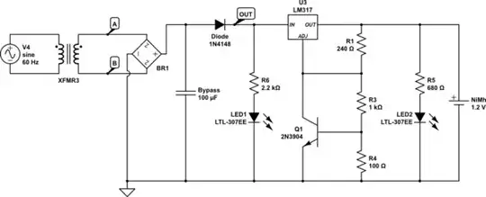
simulate this circuit – Schematic created using CircuitLab