2

My understanding is that if source resistance is low, a bipolar op amp has 10dB less noise than a JFET. I prefer the JFET op amps because the input offset is so low that you can eliminate coupling capacitors and associated componentry.

So is there a bipolar op amp that has a low enough offset that stages can be DC coupled? Even when using a large pull down resistor on the + input a for high impedance input stage?

This would be for audio BTW.

UPDATE: The following circuit is identical to Figure 14.1 of Small Signal Audio Design by Douglas Self minus the output cap and missing output load resistor which are 47uF and 22K in the book.

Line Input Stage from D. Self book

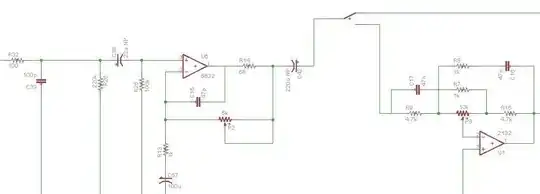
The next circuit is the circuit that I'm planning to actually use and is largely a combination of 2-3 circuits from the aforementioned book. I believe this circuit shows the impedance environment surrounding the 200uF cap that might be eliminated if a suitable op amp were to be identified. Vertical lines that run off the bottom are to ground.

line input similar to figure in D. Self book

squarewav
  • 1,440
  • 1
  • 14
  • 33
  • 5
    Don't design by "I hear bipolar op amps have less noise, so..." Instead, let's talk about the jfet amp you would use, and shoot for something 10dB quieter, regardless of what the underlying technology is. How big is the gain, how much offset can you tolerate, and how much noise? Also, do you need a single-sided rail-to-rail, or do you have positive and negative power? – Scott Seidman May 15 '13 at 20:20
  • 3
    DC coupling for an audio application isn't necessary unless you are one of the god-class audiophiles that light our collective lives with their esoteric wisdom. – Andy aka May 15 '13 at 21:30
  • 1
    @ScottSeidman The fact is that at the low end of the price spectrum, say TL072 vs NE5532, bipolar input opamps have less noise for the same source and input impedances than JFET input opamps. There's really no way to "design" around the shortcomings of JFET input opamps for the same audio input stage requirements if cost is an object. – MattyZ May 15 '13 at 21:52
  • @Bitrex I'm saying, and let this be clear, DC coupling of stages is NOT needed for Audio... the rest of my comment (above) was borderline humour (LOL) – Andy aka May 15 '13 at 22:10
  • @Andyaka Sorry! Looks like I misread your comment. I apologize! – MattyZ May 15 '13 at 22:15
  • @Bitrex, never meant to imply that a bipolar op amp isn't the answer. Cost is one design input, noise and offset are some others, but the type of ic you choose to do the job isn't (unless driven by something like a design contest). The process is to carefully generate specs, and then design to them. Short circuiting the process can mean unneccessary iterations. – Scott Seidman May 15 '13 at 23:39
  • DC coupling of stages is not needed in Audio. But DC coupling is something extra. Likewise, AC coupling is not needed in audio (not as much as people think). If we can replace a coupler by a short circuit, and everything is cool, then we basically should. – Kaz May 16 '13 at 00:35
  • 2
    There are other ways to avoid DC offsets. Adding in the output of an inverting integrator, for example, or feeding it back as a DC servo. – user207421 May 16 '13 at 03:34

3 Answers3

2

In addition to what Kaz said (this not being much of an issue in audio), you can externally compensate the offset voltage and input bias currents of any BJT-based [or other kind of] opamp. The ON Semi app note AND8177/D (formerly Philips/Signetics appnote AN142) has some basic circuits for that purpose on its last page(s). They are nominally showing the NE5534 there, but those circuits don't use anything but the signal input pins to achieve compensation, so they'd work for any BJT-based amp, including the NE5532. I have played with the first two circuits in LTSpice (with the rather basic NE5532 model found on the interwebz); they are a little sensitive to the pot values. The real issue is to quantify "near zero" (from the OP question) in an actual application...

Beware that both appnotes, even though they've been in print for 30 years, still have a bug in their offset-nulling inverting circuit with the opamp input pins being swapped. I'm referring to fig 18 in AN142 and its copy fig 22 in AND8177; you surely don't want to build a Schmitt trigger here...

Below is my test fixture for the NE5532 combining V offset and input bias compensation (somewhat spiffed for public communication from my old scratch version). This is a basic circuit, not something elaborate using DC servos etc., but I think it's good for learning what's going on; at least for me it was so.enter image description here
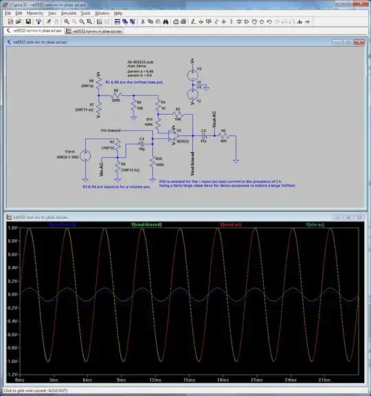
R11 provides bulk bias current compensation for R10, i.e. you want these roughly matched. Note that without C4 you will have a hard time finding a good value for R11. That's because the positive pin will see variable resistance to its left... (This is where more elaborate solutions using active components come in, but I'm not going into that.)

The fine tuning of the Voffset is via the pot "a" simulated by R7&R8, which is lifted from the aforementioned appnotes. With the pot "a" set to 0.45 (normalized value) the offset is in the few microvolts range, which for audio output is excellent.

       --- Operating Point ---

V(n002):     0.000514795     voltage
V(n003):     1.47903e-005    voltage
V(vout-biased):  -3.03485e-006   voltage
V(vin-ac):   -4.48332e-016   voltage
V(n005):     0   voltage
V(vout-ac):  -8.55829e-020   voltage
V(vin-biased):   -0.0498147  voltage
V(v-):   -12     voltage
V(v+):   12  voltage
V(n004):     -0.0498075  voltage
V(n001):     1.13011     voltage
I(C5):   1.42638e-022    device_current
I(C4):   4.98147e-019    device_current
I(R11):  4.98223e-007    device_current
I(R10):  -4.98147e-007   device_current
I(R9):   5.64796e-006    device_current
I(R8):   0.000483106     device_current
I(R7):   0.000477458     device_current
I(R6):   5.14795e-006    device_current
I(R5):   1.42638e-022    device_current
I(R4):   -4.48332e-019   device_current
I(R3):   -4.98147e-020   device_current
I(R2):   -1.78251e-009   device_current
I(R1):   5.00005e-007    device_current
I(Vtest):    -4.98147e-020   device_current
I(V2):   -0.00370861     device_current
I(V1):   -0.00370444     device_current
Ix(u2:1):    4.98147e-007    subckt_current
Ix(u2:2):    4.98223e-007    subckt_current
Ix(u2:3):    0.0032255   subckt_current
Ix(u2:4):    -0.00322698     subckt_current
Ix(u2:5):    1.78251e-009    subckt_current

The LTspice asc source file format is actually an ASCII (plain text) format, so I've uploaded the circuit (asc) to http://pastebin.com/0PzpUbFC in case anybody else finds use for it.

And below is a slight modification graphing the DC output offset as function of the offset pot position, i.e. a pot sweep. The output voltage corresponding to the "500m" (0.5 that is) pot position is basically the typical NE5332 offset votage (0.5mV) roughly multiplied by this circuit's gain (~10), resulting in about 5mV output offset.enter image description here
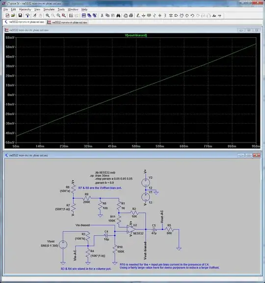
If you want to increase the effective range of the offset pot (for example if you get a really bad NE5532 that has almost 10x its typical offset) you can decrease R9; decreasing R9 to 100K would roughly double the output voltage offset range that the pot sweeps.

Also, removing R11 is a pretty bad idea; you will get hundreds of mV output offset which the offset pot cannot compensate for... as shown below.enter image description here
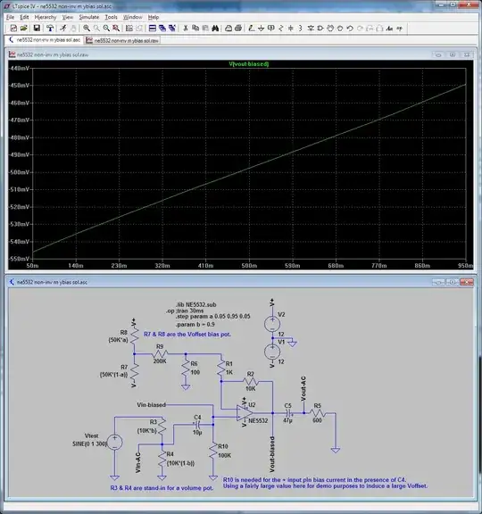
The point to remember here is that both input currents and input offset need to be cared for in the same circuit as they both affect the output voltage offset; that's something perhaps not well conveyed in the aforementioned appnote...

And perhaps more directly answering the question as asked, there are some bipolar opamps where the manufacturer has tried to center the VOS to 0... statistically. You still have to deal with non-zero dispersion. For example the OPA551/OPA552 data sheet, which gives the typical VOS values as +/-1mA and a max of +/-3mA later has the following bell-shaped (Gaussian distribution) graph.enter image description here
You also have to consider that the offset voltage may (or may not) increase much with temperature. This is again where active solutions (servos) win over manual trimming. The graph for the temperature drift of the OPA551/2 samples follows.enter image description here
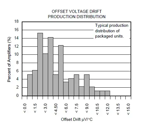
I'm not sure what shape to ascribe to this; perhaps a form of Weibull distribution for some suitably chosen parameters.

Finally, the LM4562 mentioned (by someone else) above has the bias currents measured in dozens of nA (typical 10nA, max 72nA), whereas for the OPA551 it is in the range of dozens of pA (typical 20pA, max 100pA). Having said this, I come back to my opening point: you have to ask yourself, when was the last time you've heard or read that someone was preferring a specific opamp in an audio application because of its low offset voltage and/or low input bias currents...
Fizz
  • 14,355
  • 2
  • 43
  • 97
1

The sky really is the limit when it comes to op-amps - it is definitely possible to find audio bipolar op amps that have low offsets, tiny input bias currents, and low noise. A quick Google search turns up the LM4562, which has better input bias current specs than the NE5532 by two orders of magnitude. It also costs about 5 times as much. Whatever esoteric audio amp you pick, you probably won't save any money by eliminating the coupling caps.

If the coupling caps are offensive to you from a perceived quality point of view (capacitor distortion does exist, but I'm certainly not going to get into a debate about its subjective effects), and you're determined to remove them, then you have to qualify your question by stating how much you're willing to pay to include this "feature." This will probably also require some details about what sort of product you're designing.

In short, the answer to your question:

"So is there a bipolar op amp that has a low enough offset that stages can be DC coupled?"

is "Yes," but any futher comment on what to use or how to use it requires more information.

P.S. It is possible to obtain high input impedance with low-value resistances when using a bipolar device by using a bootstrap circuit (assuming positive and negative supplies):

schematic

simulate this circuit – Schematic created using CircuitLab

I don't know if C1 counts as a coupling capacitor to you; it's possible to eliminate it using another op-amp section.

MattyZ
  • 2,926
  • 1
  • 22
  • 23
  • Clever. But would this not significantly affect the output impedance. INAEE but my spider sense just twinkles when I look at that cap. – squarewav May 15 '13 at 23:12
  • I'm not designing a product - I'm creating a one-off hand-wired circuit so cost is not a great concern (although I'm not an audiophool so you probably won't catch me buying a $20 op amp). When it comes to analog circuits, my experience is that the best noise performance is obtained by 1) large dynamic range so I'm using +-15V and 2) small resistors / low impedance so I try to use minimal circuitry or passive components like inductors which add very little noise. So the problem with coupling caps is that they have to be relatively large (220uF BP) which makes hand-wiring a little more difficult – squarewav May 15 '13 at 23:22
  • @ioplex The bootstrap is to increase input impedance. It won't affect the output impedance. I don't think that there's a danger of the circuit oscillating (at least it doesn't in simulation) - R2 ensures that the phase shift is low at high frequencies. If there's a concern one can always decouple the capacitor form the output by inserting a small valued resistor between them. – MattyZ May 15 '13 at 23:31
  • 1
    @ioplex If you have an input stage that you think needs a 220uF capacitor, there is no way that its resistors can be high enough develop any non-negligible voltages from bias currents, regardless of what op-amp it is. Also, if you need 220uF in order to pass 20 Hz well (-3dB rolloff point at f/10, or 2Hz), it means that the input impedance must be only 360 ohms. That is likely hard to drive by whatever op-amp is feeding it. – Kaz May 16 '13 at 00:47
  • @Kaz The 220uF would not be used in combination with the high impedance input. It is used to drive an inverting stage that has very low input impedance (a "tilt" control in the extreme high pass position) of about 700 ohms. I realize a smaller capacitor would also work but simulations showed that the larger capacitor reduced low frequncy noise. I believe this rationale is supported by circuits in Small Signal Audio Design by Douglas Self. – squarewav May 16 '13 at 01:13
  • @ioplex A filter, I see. But how bad is the actual DC offset there? How many millivolts are we talking? – Kaz May 16 '13 at 01:28
1

Almost all op-amps have low enough offsets that you can couple stages without capacitors at every single coupling, especially if the gains are reasonably low. That is to say, accumulate a bit of offset over several stages.

I've used megohm resistors on the + input of NE5532 op-amps without any problems. So many hundreds of nanoampers of bias current across a million ohms is only so many hundreds of millivolts of offset. On +/-15V power rails, barely noticeable; a non-issue.

Anyway, you don't need a million ohms of impedance for most audio. When I hear about large impedances at the input stage, I assume that it's for guitar. (Is that true?) Guitar pickups are badly designed but that's part of their sound and we are stuck with them. Microphones do not need high impedances, and neither do line-level couplings. Excessively high impedance is harmful in audio, because it magnifies cable capacitance. In most audio coupling applications, anything over 10K is a waste. The reason is that we have decently low (near zero) output impedances already. You do not need both near-zero output impedance and ridiculously high input impedance, just one of the two!

If you don't opt for ridiculous input impedance, you are more free to use inverting stages, which have several advantages over noninverting ones, such as avoiding common mode input movement.

Kaz
  • 19,838
  • 1
  • 39
  • 82
  • I'm not actually looking for "rediculously high" input impedance. I was just thinking that if the op amp had a low offset with a large pull-down resistor, then it should be able to handle more realistic cases with ease. The target circuit in question would be very much like Figure 14.1 in Douglas Self's Small Signal Audio Design. That input impedance is 200K||100K = 68K. At this point I'm lifting most of my circuits almost verbatim from this book. I'm just wondering if I can simplify things with a better op amp. – squarewav May 16 '13 at 01:28
  • @ioplex - maybe, you can post the circuit you are referring to in fig 14.1 and any of the other circuits you are considering. I'm genuinely interested. I took a few minutes to read comments on his books and although they seemed to be made by amateurs I'm intrigued to discover what your circuit is all about. – Andy aka May 16 '13 at 07:13
  • 68K of impedance is not large; you do not have to worry about an offset from that in audio circuits no matter what op amp you use. (What's 500 nanoamps times 68K? Only 0.034V!) And 68K is small enough that, in your noninverting configuration, you can just use a similar resistance in the feedback. Then any remaining offset attributable to bias currents is due to their difference. The difference between bias currents from the two inputs is smaller than their absolute value. Doug Self is quite thorough so if this was important, he would fuss over it and include the compensation in the circuits. – Kaz May 16 '13 at 18:56
  • @Andy aka added circuits above. – squarewav May 16 '13 at 19:04
  • @Kaz Actually it's 100k (see circuit above) but regardless I'm not sure I believe the offsets wouldn't matter that much. I think that even that relatively small current running from one stage to the next might have some kind of impact (eg potentiometer wiper noise). If I cannot find a part that beats the 5532 and has no offset, then I'll just use coupling caps. I was just wondering if there was a new or relatively unknown op amp out there that really beat the 5532 and had a super low offset. The LM4562 sounds very interesting but like anything, I will have to try it ... – squarewav May 16 '13 at 19:11
  • I have an NE5532-based device in which a buffer is DC coupled to a Sallen-Key low pass filter stage where R1 and R2 are a potentiometer (50K) (well not down to zero: there are some series resistors too). There is no audible wiper noise. I think wiper noises require fairly serious DC to be flowing, not fractions of a microampere. And/or serious gain. I planned for a coupling cap in the circuit, so there is a footprint on the PCB for it. But what I actually installed there was wire. That's a good strategy: *design* in footprints for couplers, but *install* judiciously. – Kaz May 16 '13 at 19:44