The driver appears to be ICL7136 as @RedGrittyBrick has observed.
This driver doesn't output its data in a readily readable format, but is designed to drive an LCD directly.
There is one output pins for each of the LCD segments:
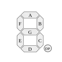
(No decimal place is output. Decimal must be hardwired by the designer according to the range of the application I guess.)
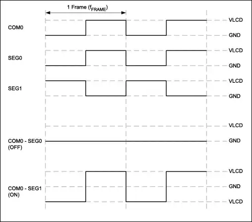
So the signals are output like this, but they are inverted when the backplane (BP) signal is high. This is to drive the LCD signal with an AC voltage.
Wikipedia has a truth table of seven-segment values. These can be used to construct a lookup table to transform the values back to the number.
Notice the leading "1" and the negative sign are just single bit outputs (AB4 and POL, respectively).
So we would like to sample the segment values, but half the time they will be inverted.
Here's one way to get ICL7136 data into a microcontroller. This uses three latches to hold the data lines. The data is latched on the rising edge of the backplane signal, so it is inverted.
To read digit one, SEG1 is brought high and SEG2 and SEG3 are held low. Then the state of the LCD segments can be read from ABCDEFM. Likewise for the other two digits. (M holds POL and AB4 values as per schematic.)