17

I've been trying to find a good description of the TTL serial "standard" without much luck. I understand that serial transmit (TX) and receive (RX) lines idle high (at VCC) and that they drop to ground when a bit is transmitted. As such, they're inverted from the norm, where a "1" is high and "0" is low.

What I don't understand is who's responsible for holding the line high and how a zero is transmitted. Does the sender drive the line to high and low? Or does the receiver hold the line high with the sender pulling the line low (open collector)?

blalor
  • 2,544
  • 3
  • 22
  • 24
  • Read Joby's answer; apparently everything I thought I knew was inverted. :-) – blalor Nov 17 '10 at 16:04
  • Real RS232 is the other way around 0 = 12v, 1 = -12v, that's why it's confusing – Toby Jaffey Nov 17 '10 at 16:34
  • 2
    Point of terminology: "TTL serial" is a severely over-broad term, "(point-to-point) asynchronous serial (at TTL levels)" seems to be what you're asking about. (Though that's still probably lacking, but at least better) – Nick T Nov 17 '10 at 18:42
  • 3
    @Nick The kind the OP means is whatever is fed into a MAX232, I'd call that "RS232 at TTL levels" – Toby Jaffey Nov 17 '10 at 21:56
  • 2
    @Joby - If he uses only Tx and Rx, and you also remove its levels, then there's nothing RS232 anymore about it! Call it UART. – stevenvh May 11 '12 at 10:40

2 Answers2

19

With TTL serial, there are two unidirectional data lines. Each is driven by the sender, both high and low. A 0 bit is represented by 0V a 1 bit by VCC.

The receiver's pin should be set to an input.

So, for a microcontroller to send a byte (8-N-1 no flow control) it could do something like this:

#define BAUDRATE 9600
#define DELAY (SYS_CLK/BAUDRATE)

#define UART_BITBANG_OFF     UART_BITBANG_PORT |= _BV(UART_BITBANG_PIN)
#define UART_BITBANG_ON      UART_BITBANG_PORT &= ~ _BV(UART_BITBANG_PIN)

#define UART_BITBANG_BIT(bit) {if (bit) UART_BITBANG_ON; else UART_BITBANG_OFF; _delay_us(DELAY);}

void uart_bitbang_init(void)
{
    UART_BITBANG_DDR &= ~ _BV(UART_BITBANG_PIN);        // TX output
}

void uart_bitbang_putc(uint8_t c)
{
    UART_BITBANG_BIT(1)
    UART_BITBANG_BIT((c & 0x1) == 0);
    UART_BITBANG_BIT((c & 0x2) == 0);
    UART_BITBANG_BIT((c & 0x4) == 0);
    UART_BITBANG_BIT((c & 0x8) == 0);
    UART_BITBANG_BIT((c & 0x10) == 0);
    UART_BITBANG_BIT((c & 0x20) == 0);
    UART_BITBANG_BIT((c & 0x40) == 0);
    UART_BITBANG_BIT((c & 0x80) == 0);
    UART_BITBANG_BIT(0);
}

(This code reads a bit backwards as it was originally meant for inverted TTL serial)

Of course, most MCUs have hardware UARTs which do all this for you.

Here's what you'd see on a scope:

https://www.pololu.com/docs/0J25/4.a

Here's a great video from ladyada explaining serial: http://www.adafruit.com/blog/2010/09/15/usb-serial-and-you-video-an-adafruit-after-school-special/

Toby Jaffey
  • 28,796
  • 19
  • 96
  • 150
  • Thanks, Joby. So even though the line idles high, a 0 bit is still 0v. Does the receiver typically have an internal pull-up on the RX line, so that it doesn't float? – blalor Nov 17 '10 at 16:06
  • @blalor the line won't float, the sender is driving it (assuming both ends are connected) – Toby Jaffey Nov 17 '10 at 16:21
  • Arduino's NewSoftSerial enables the AVR's internal pull-up on the RX pin. I assume this *is* required if there isn't an attached sender. Thanks for the info, and the added Adafruit link. – blalor Nov 17 '10 at 17:11
  • 1
    Being somewhat pedantic, but doesn't "TTL" just imply levels? You describe a point-to-point serial link, but could it just as well be a multi-master topology with open collector drivers and a pullup (like LIN but with TTL levels)? "TTL serial" seems like an *incredibly* broad term that's almost useless without some context. – Nick T Nov 17 '10 at 18:36
  • 1
    It's just the standard serial port interface with the voltage converters removed. – starblue Nov 17 '10 at 21:47
8

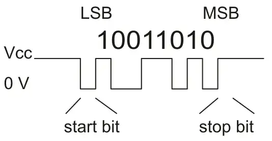
You don't say in so many words, but the "idle high" suggests you mean a UART. UARTs a point-to-point connected to line-transceivers, like the ubiquitous but dated MAX232 (there are far better solutions nowadays). The line between microcontroller and transceiver will also be short; if there's distance to be bridged it will be between transceivers.
The controller's output is a push-pull.

enter image description here

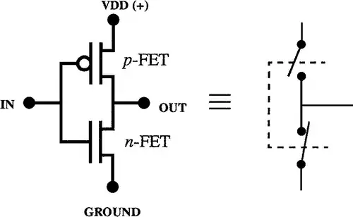
The P-MOSFET will provide the high level, the N-MOSFET the low level. One of them must be active or the line level would float and be undefined (or defined by a load in the transceiver). Both are able to source/sink some current and will pull the line to the rails, so the signal shape will almost be ideal.
Which would be different if it were really TTL, as in your question (the microcontroller is HCMOS). TTL outputs are highly asymmetrical: they can only supply little current, typically 0.4mA. Sinking current is OK, at 8mA. The low source current may be a problem if the line has a high capacitance and is high speed. The low drive current means that the capacitance will only charge relatively slowly, and rising edges will be slow, which at high speed may cause serious signal distortion. TTL is never used for this.

Your question could also refer to a multidrop line, where several devices can talk. In that case you can't use the push-pull output: if one device would drive the line high while another drives it low we would have a short-circuit. Multidrop lines almost always use pull-up resistors to keep the line idle high. Then only a low level requires driving the line, and instead of the push-pull output we'll have an open-drain, with just the N-MOSFET. The line is now also driven asymmetrically: the pull-up resistor can only deliver little current, while the pull-down FET can drive the line fast to ground. High speed multidrop lines therefore put a limit to the pull-up resistors. An example is I2C.

stevenvh
  • 145,145
  • 21
  • 455
  • 667
  • "the ubiquitous but dated MAX232 (there are far better solutions nowadays)" Could you give some examples? – m.Alin May 11 '12 at 10:28
  • 3
    @m.Alin - [Says Maxim](http://www.maxim-ic.com/app-notes/index.mvp/id/2020): "Many board designers still use the MAX232 today, despite the fact that single-supply devices have undergone extensive improvements over the years.". [List of transceivers](http://para.maxim-ic.com/en/search.mvp?fam=rs232&tree=master) – stevenvh May 11 '12 at 10:38