3

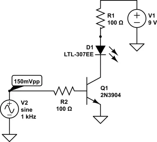
I would like to control an LED with audio signal, but the problem is, that output signal is only 150mVpp (with 150mVpp positive offset). In my understanding, it needs to be higher than 0.6V to get the transistor running, therefore I am not sure what to use instead. Do I maybe need an opamp in the middle? Any tips?

schematic

simulate this circuit – Schematic created using CircuitLab

mrkva
  • 445
  • 1
  • 6
  • 14
  • 2
    By "control an LED", do you mean the LED should be on when there is an audio signal, and off when there isn't, or something more sophisticated such as intensity controlled by signal strength? – Anindo Ghosh May 11 '13 at 13:22
  • You want to control the LED...to do what? – Phil Frost May 11 '13 at 13:22
  • @PhilFrost That was neck to neck comment timing! – Anindo Ghosh May 11 '13 at 13:22
  • +1 to counter the drive-by down-vote. If there's a need for a downvote, please consider leaving a comment explaining why, it helps new members improve their questions (and answers) for the future. – Anindo Ghosh May 11 '13 at 13:29
  • Controlling LED - it should be ON lets say when the AC voltage on the left is in 100-300mV – mrkva May 11 '13 at 13:34

2 Answers2

2

Here is an approach using a comparator and minimum additional components, that would serve the purpose.

The key active part is an open collector comparator such as the Linear Technologies LT1011. Substitute this with any open collector / open drain comparator that operates with a single supply ranging beyond 9 Volts.
schematic

simulate this circuit – Schematic created using CircuitLab

  • The "Bias Setting" block sets an adjustable bias voltage for the signal.
  • The Peak Detector block detects peaks of the signal including the DC bias added in the previous block. Thus, the resultant voltage is DC_Bias + V1_peak - V_diode.
  • Adjust the bias such that the DC_Bias - V_diode value is just below the voltage of the voltage divider made up of R3 and R4. When the 75 mV peak input signal is added to it, the result will be just above comparator threshold
  • The comparator is an open drain, so it will allow current through the LED + R5 when the output is conducting. If the sense (on v/s off) is inverted, simply interchange the + and - inputs of the comparator.
  • Totem pole or other comparators will work as well with minor or no changes to the output side if those comparators are more easily available than an open drain / open collector one.
Anindo Ghosh
  • 50,188
  • 8
  • 103
  • 200
1

Here's a link to a previous post that I answered and this was the circuit that I used many moons ago for an audio detector that was quite low quiescent current and turned a battery amplifier on when a signal was detected: -

enter image description here

Although the previous question mentions a microphone it is a line-audio ac detector circuit and also ran from a 9V battery.

Andy aka
  • 434,556
  • 28
  • 351
  • 777