4

I am trying to control a MCP4131 digital pot from my Raspberry Pi using this library.

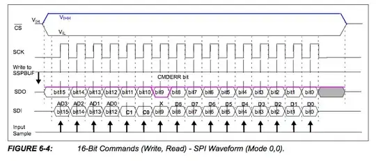
Using the GPIO pins, I am "emulating" an SPI interface. I bring the ChipSelect pin to low, write my byte, then bring it high again.

When I plug my meter into the wiper, I get a constant voltage. It's not changing. Is there something wrong with my code in POT.cs?

class Program {
    static void Main(string[] args) {

        GPIOMem cs = new GPIOMem(GPIOPins.GPIO_17);
        GPIOMem clock = new GPIOMem(GPIOPins.GPIO_23);
        GPIOMem sdisdo = new GPIOMem(GPIOPins.GPIO_22);

        var pot = new POT(clock, sdisdo, cs);

        while (true) {
            for (uint level = 0; level <= 127; level++) {
                pot.SetValue(level);
                Thread.Sleep(100);
            }

            for (uint level = 127; level >= 0; level--) {
                pot.SetValue(level);
                Thread.Sleep(100);
            }
        }           
    }
}

Pot.cs

public class POT {
    private GPIO clockpin;
    private GPIO mosipin;        
    private GPIO cspin;

  public POT(GPIO SPICLK, GPIO SPIMOSI, GPIO SPICS) {
        clockpin = SPICLK;
        mosipin = SPIMOSI;
        cspin = SPICS;
    }

    public void SetValue(uint value) {
        Console.WriteLine("here");
        cspin.Write(true);

        clockpin.Write(false); // #start clock low
        cspin.Write(false); // #bring CS low

        BitArray b = new BitArray(BitConverter.GetBytes(value));
        Console.WriteLine(value);
        for (int i = 8; i > 0; i--) {
            mosipin.Write(b[i]);
            clockpin.Write(true); //cycle the clock
            clockpin.Write(false); //yucle the clock
        }
        cspin.Write(true);
    }
}

Please note: all the 3 GPIO pins are working as they should.

Nick Alexeev
  • 37,739
  • 17
  • 97
  • 230
Chris Kooken
  • 251
  • 5
  • 15
  • 1
    Since you are doing this manually, you should be able to make it single step (perhaps with the return key?) and probe the lines (wire LEDs to them, etc) and verify that they are changing in the necessary sequence. Or once you've verified control of the lines, you can just print out a table of the settings on the console each time you change them and verify from that. – Chris Stratton May 10 '13 at 15:17
  • I see no delays in your SetValue routine. You are toggling the SPI lines at maximum speed which is very likely faster than the SPI slave can handle. – DoxyLover May 10 '13 at 16:15
  • BusPirate is your friend. Or just an oscilloscope. – John U May 10 '13 at 16:15
  • 1
    I stepped through it..one line at a time, and all the values are writing correctly. I ordered a bus pirate off amazon, hopefully that will help. – Chris Kooken May 10 '13 at 17:38
  • 1
    Please show schematic of how the digital pot is connected. – markrages May 10 '13 at 23:59
  • You do know you need to apply voltage across the pot before you will measure a voltage on the wiper, right? It's not a DAC. – Connor Wolf May 11 '13 at 03:46
  • 1
    Chris - Would you please post your final working pinouts and code for the MCP4131 and Raspberry Pi? The community would really appreciate it - thx! –  Jun 25 '13 at 02:13
  • What clock rate are you generating there? From the data sheet, it appears that the MCP4131 expects a max clock rate of 10MHz, wouldn’t a Raspberry Pi operating at 700MHz generate a clock quite a bit faster than that with the above code? – microtherion May 10 '13 at 16:13
  • @microtherion Do I need to sleep between two `cloclpin.write` lines? – Chris Kooken May 10 '13 at 16:18
  • Might be best to sleep after each `clockpin.Write`. Start with a sleep of 1µs or so, and if that works, try moving toward the theoretical minimum of 50ns. – microtherion May 10 '13 at 16:29
  • @microtherion I've increased the timing delay and no change...still not working. – Chris Kooken May 10 '13 at 17:38

1 Answers1

4

The MCP4131 uses an annoying "multiplexed" SPI implementation.

enter image description here

To write to the MCP4131, you cannot just write 8 bits. You need to write 16 bits. They are described in the datasheet.

enter image description here

You will want to use address 0 (Volatile wiper #0) and command 0, with the data being your value prefixed by zeroes. In other words, clock out eight zero bits before your value and you'll be OK.

enter image description here

I wish Microchip didn't put all their SPI digital pots into one datasheet. It makes the datasheet harder to read.

Also, double check the voltage across P0A and P0B (the ends of the resistor). If you don't have voltage there, changing the pot tap won't change the wiper voltage.

microtherion
  • 1,571
  • 2
  • 11
  • 18
markrages
  • 19,905
  • 7
  • 59
  • 96
  • Awesome, that worked. Thank you so much! What is the purpose of the "multiplexed" implementation. Why do they even do it? – Chris Kooken May 11 '13 at 16:29