41

I have an N-MOSFET gate connected to a 4043 logic. Id is about 100 mA. Both the 4043 and MOSFET have +5 V. I plan to use a 2N7000.

  • How large a gate resistor do I need between the 4043 and MOSFET? The logic output is sometimes switched rapidly. How fast? A motherboard HDD LED controls it.

  • Do I need to place pull down resistor from logic to 0 V, between the 4043 and the MOSFET?

JYelton
  • 32,302
  • 33
  • 134
  • 249
hanukas
  • 413
  • 1
  • 4
  • 5
  • 1
    The answers by jippie and PhilFrost are good, but if you would like to get a more quantitative view of gate resistance in MOSFETs you could look at this post (http://electronics.stackexchange.com/questions/60427/calculating-the-pulldown-resistance-for-a-given-mosfets-gate?rq=1). – gsills May 11 '13 at 20:20
  • It also depends what the MOSFET's load is: http://irf.custhelp.com/app/answers/detail/a_id/215 – Fizz Nov 08 '15 at 13:45
  • If the logic never gets abruptly disconnected from the MOSFET, such as when having two instruments connected with a cable, you can do without any resistors here. The CMOS 4000 line is push-pull, so no pull-up/down resistors are needed. And unless your MOSFET is used on the edge of its capabilities, you don't need to worry about the added cable capacity either. – Zdenek Nov 10 '17 at 20:35

3 Answers3

48

It is generally a good idea to include a gate resistor to avoid ringing. Ringing (parasitic oscillation) is caused by the gate capacitance in series with the connecting wire's inductance and can cause the transistor to dissipate excessive power because it doesn't turn on quickly enough and hence the current through drain/source in combination with the somewhat high'ish drain-source impedance will heat the device up. A low ohm resistor will solve (dampen) the ringing.

As @PhilFrost mentiones, a high value resistor to ground is a good idea to avoid capacitive coupling driving the transistor when it is otherwise not connected.

schematic

simulate this circuit – Schematic created using CircuitLab

At all times keep the wiring between logic output, transistor gate, transistor source and ground as short as possible. This will ensure fast turn on/off.

jippie
  • 33,033
  • 16
  • 93
  • 160
  • 8
    A trivial observation: I would put the pull-down resistor before the gate limiting resistor - that way, the two resistors do not form a voltage divider (however minor), and thus the input voltage is fully expressed at the gate. – Anindo Ghosh May 10 '13 at 05:52
  • 1
    @AnindoGhosh This was discussed in [an answer](http://electronics.stackexchange.com/a/30044/5035) to [one of](http://electronics.stackexchange.com/q/30017/5035) my questions. supercat noted that putting R2 before R1 creates a voltage divider when the G-D is shorted in case of MOSFET failure and thus, protect the driver a little. Of course, the values should be selected appropriately and there is a power consumption trade-off. – abdullah kahraman May 10 '13 at 06:31
  • 4
    @abdullahkahraman The driver would be protected in either case, R2 before or after - the protection is courtesy the R1. – Anindo Ghosh May 10 '13 at 06:40
  • @AnindoGhosh never really considered an alternative location for R2 and although the voltage division is minimal I guess you are right. For protection of the microcontroller when D-G shorts out, a 5V1 zener can be placed in parallel to R2. Not sure how effective it is, but at least you took a shot a protecting the controller. – jippie May 10 '13 at 06:56
  • 2
    @Anindo I actually prefer the series resistor near the source and let it double as source terminator. The voltage divider is a non-issue (100/1M = 0.01%, not even 1mV for a 5V driver). – apalopohapa May 12 '13 at 06:14
  • 1
    @apalopohapa True for the values in the current design, but not necessarily true for a lower value pull-down or a higher value limiting resistor. I have had occasion to apply either or both those cases. YMMV, of course :-) – Anindo Ghosh May 12 '13 at 06:27
  • The logic behind using a 1Meg Gate load is absurd, and the resistor is entirely unnecessary for any driver circuit that has active pull-down. The primary utility of a Gate series resistance is reduced turn-on and turn-off rate of M1. –  Nov 08 '13 at 15:09
  • Minimum resistor value to avoid ringing can be determined if one knows the trace/wire inductance going to the MOSFET's gate as seen in [this appnote](https://www.power.com/sites/default/files/product_document/application_note/AN-1001_IGBT_and_MOSFET_Drivers_Correctly_Calculated.pdf) for example, but in practice it may be hard to measure inductance that low. – Fizz Nov 08 '15 at 14:03
21

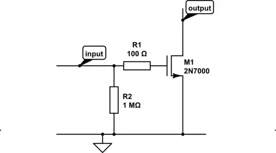
You do not strictly need a base resistor. Not only do MOSFETs not have bases (they have gates), but the gate is (very) high impedance. Except when the MOSFET is changing states, the gate current is essentially zero.

Sometimes, a gate resistor is prudent to reduce ringing, especially if the trace driving the gate is long, or if you are concerned with generating electromagnetic interference. A higher value dampens ringing but also slows switching times: the appropriate value depends on how bad the ringing could potentially be and what switching times are required.

It is common practice to place a resistor (the value isn't terribly critical -- anything between \$ 1k\Omega \$ and \$1M\Omega\$ will do) from the gate to ground, just to be sure the MOSFET will be off if the thing driving it (the 4043 in your case) is letting the output float. Otherwise, very small currents from your finger, capacitive coupling, inductive coupling, or other things you'd rather not worry about can change the gate voltage of the MOSFET, resulting in unintended behavior.

Phil Frost
  • 56,804
  • 17
  • 141
  • 262
  • 3
    I think to limit the inrush current, one should put a series resistor, when working with microcontrollers. Or is it just overkill ? – abdullah kahraman May 09 '13 at 17:15
  • 1
    @abdullahkahraman I/O ports are generally not stiff sources and sinks, so I don't see a need for a series resistor. – Adam Lawrence May 09 '13 at 17:20
  • 2
    Sometimes you do put a small (100-200 ohms) resistor, or maybe a ferrite bead, in series with a MOSFET gate in order to kill the gain at high frequencies (RF) if it is showing signs of instability. – Dave Tweed May 09 '13 at 18:16
  • @Madmanguruman -- Using the internal channel resistance of the I/O driver (e.g. no external resistance) is a *risky* plan since you are dissipating all of the energy into the relatively fragile die. If the FET gate you are driving is large (very capacitive) and your drive frequency is high (as in PWM/motor-control applications) you will burn out the I/O driver. – DrFriedParts May 09 '13 at 18:56
  • @DrFriedParts The limited current from a GPIO would make driving a large-capacitance MOSFET at high frequency impossible, necessitating an external driver. If the die is too fragile to handle the rated I/O current of the GPIO, that to me is a sign of lack of robustness. – Adam Lawrence May 09 '13 at 18:59
  • 11
    I'd like to remind everyone that we are talking about driving a 2N7000 with a 4043. Neither is the 2N7000 a high gate charge device nor is the 4043 capable of high drive currents. I seriously doubt this combination requires a gate resistor any more than all the MOSFETs in a CPU require gate resistors. – Phil Frost May 09 '13 at 19:12
  • 1
    Hahaha, thanks for the heads up Phil, we almost did not notice. This is what happens when bunch of engineers come together, lol. – abdullah kahraman May 10 '13 at 06:27
  • 4
    @Madmanguruman -- Your conclusion is correct given your assumptions, but your assumptions don't apply in most consumer-grade MCU's. (1) You can (and will) exceed rated I/O current if you short the output driver. (2) The driver will behave as if driving into a short circuit if the switching frequency is high -- the input can switch at high frequency independently from the output. The output won't climb much in response resulting in a sustained short-like condition. However, Phil is correct, that isn't the case here, but your generalization deserved this qualification. – DrFriedParts May 10 '13 at 07:06
  • @Madmanguruman - If an xxx is too yyy to handle the zzz of a nnn, that to me is a sign of lack of robustness :-). – Russell McMahon May 12 '13 at 16:09
  • I should have studied "pedantics" instead of "electronics". Sheesh. – Adam Lawrence May 12 '13 at 16:20
  • 1
    If you don't put a series resistor you will never pass emc tests because the ringing will cause interference all over the place (you will not see it when measuring signal on the wire but with an emc probe you will see the havoc it creates) – Martin Jun 28 '19 at 06:56
  • Doesn't anyone use parasitic chokes any more? I suppose they are a bit passé, but in the old days we'd wind a few turns of copper wire around the body of a resistor (see: old days). I suppose a ferrite bead serves that purpose now? – holdenweb May 24 '20 at 11:19
0

A MOSFET gate acts as a capacitor, and charging currents can exceed 200ma. A 100 ohm (3v) to 200 ohm (5v) series resistor keeps this around the 20ma mark. A 10k pulldown resistor ensures shutoff if gate floats.

sspence65
  • 1
  • 1