6

I have a generator that supplies a constant DC 10A current to a NiMH battery pack with 240 cells in series (nominal voltage of DC 288V). This current is too high for any cell once it has reached 100% state of charge (SoC), but I am required to charge past 100% in order to 'top-end balance' the series string of battery cells.

I want to limit this charging current to 1A so that the cells that have already hit 100% SoC don't have to dissipate 10A, which would most likely result in hot electrolyte being vented, and permanent damage to the cell. At 1A charging current the cells that are at 100% SoC can dissipate the current as heat without venting.

I have no way of reducing 10A charging current as the generator's software and control system are locked down. The generator expects to supply 10A and uses a hall effect sensor to make sure that is what it is supplying.

The only way I can see this working is that I waste 9A if the 10A, all I want to know is how to dump this 9A of current, with the remaining 1A going to the battery.

Apart from the rare occasion I need to do a battery balance it is essential that the hall effect sensor is reading correctly. I also need this to be a permanent solution, so rewiring the sensor is not an option. I need a solution that can be bypassed most of the time (such as with a relay/switch), then activated on the rare occasion that I need to balance the battery.

It's a very rare occasion that I will balancing the battery so I don't care that 9A of current is being completely wasted into a resistive load.

Could I use a resistive load in parallel with the battery, or perhaps buffer the generator input current with a capacitor, then switch between a resistive load that will draw 10A for 9/10ths of the time, and then to the battery for 1/10th of the time using a relay/IGBT?


Added - RM:

Here is the lightbulb lighting (& car operating) information that helps put these questions in context. Helpfully provided buried in the comments some while after the question was asked:

  • The charger and battery is for a Toyota Prius NHW10
    (the first Prius which was only sold in Japan).

  • Battery cells are Panasonic HHR650D.
    These are 6.5Ah (when new) NimH "D" (33620) cells.
    Data sheet here

  • They may be arranged in series parallel strings as they are rated at 6.5A max fast charge, but perhaps we'll get more on that at the next information (wiki)leak.


Added - OP:

  • I can confirm that the battery is one large series string. The car itself will draw up to 110A to drive the electric motor. The highest charge current i've witnessed is a touch over 50A for very short periods of braking.
cianz
  • 63
  • 7
  • 1
    possible duplicate of [Choosing power supply, how to get the voltage and current ratings?](http://electronics.stackexchange.com/questions/34745/choosing-power-supply-how-to-get-the-voltage-and-current-ratings) – placeholder May 09 '13 at 01:32
  • I cannot change the power supply, the supply current is out of my control. – cianz May 09 '13 at 01:38
  • 3
    Read the linked post, it explains that the 10A is a Maximum. The supply current is dictated by the the battery here as long as it doesn't exceed 10A. If you are concerned that you want to limit the battery charging current to 1A only, then that is a different question, if that is the case then edit the question to reflect that. – placeholder May 09 '13 at 01:48
  • @cianz Update your post and write more details about your battery (chemistry, capacity, number of cells). There may be more to your question. – Nick Alexeev May 09 '13 at 02:25
  • I've updated my post, cheers. – cianz May 09 '13 at 02:43
  • Is your source a 10A "constant current power supply", or a "constant voltage power supply" with 10A current capacity? – apalopohapa May 09 '13 at 03:40
  • What _is_ this power supply, and why do you have to use it? – pjc50 May 09 '13 at 08:38
  • Yes, more clarification on the power supply please. If the power supply really outputs 10A and that is unchangeable, any attempt to decrease the current would make the PSU raise it's output voltage until it fried the circuit and got it's 10A back, making the only real solution a parallel circuit which dumps 9A. But I'm pretty sure this is not the case... – gbmhunter May 09 '13 at 10:30
  • On your duplicate post you mentioned a generator using a hall effect sensor to force the 10A; you might be able to loop the wire past this sensor 10 times, which will cause it to think the current is 10x what it actually is, resulting in a 1A constant current drive. – pjc50 May 09 '13 at 12:28
  • Good suggestion, but apart from the rare occasion I need to do a battery balance it is essential that the hall effect sensor is reading correctly. I also need this to be a permanent solution, so rewiring the sensor is not an option. I need a solution that can be bypassed most of the time, then activated on the rare occasion that I need to balance the battery (i'll update my question to include this - sorry for the ambiguity). – cianz May 09 '13 at 12:38
  • Another strategy: a domestic 3kW 240V heater is, fundamenally, a 1kohm resistor with a very good heat dissipation. I'm wondering what happens if you simply connect one or two in series with the battery pack; the generator must have an upper voltage it can drive to? Do you have a model number you can tell us? – pjc50 May 09 '13 at 13:50
  • It's a Toyota Prius NHW10 (the first Prius which was only sold in Japan). I've got the battery cell details too, which are Panasonic HHR650D (http://www.panasonic.com/industrial/includes/pdf/Panasonic_NiMH_HHR650D.pdf). – cianz May 09 '13 at 15:15
  • Suggested equivalent question does not address this question's key issues. || Absorbing additional current with a parallel load as required is easy [tm]. Adding a controlled series resistance to limit current may use less energy assuming energy source tolerates this - also easy enough. || Inobvious why people could not understand the question. – Russell McMahon May 09 '13 at 15:49
  • @Russell, I suspect the explanation lies in the original question before editing...it's been changed since then. Kind of a flaw in the way we do things here. – gbarry May 09 '13 at 16:55
  • Perhaps you could spoof the Hall sensor with a magnet? – gbarry May 09 '13 at 17:00
  • My initial question was very vague in hindsight, sorry about that. So a parallel load is the best way to go, any caveats on how I should go about that? Would I just calculate the resistance of the battery and then the required resistance of the parallel load? Because if I was to use a series load it would increase the voltage to the generator I take it? – cianz May 10 '13 at 00:02
  • Only very slightly rudely put useful addition made to your question. You may wish to remove the only slightly snarky bits :-) - and add some extra information. ALL information at get-go would have gone and got you a decent answer before now. – Russell McMahon May 10 '13 at 13:30

2 Answers2

5

The stated requirement can be met relatively easily. Whether that will treat the batteries as they should be treated is unknown to me, ...

A warning: "Modern" AA NimH above about 2000 mAh capacity will not tolerate even a whiff of long term trickle charging. Whereas C/10 rate was once a commonly accepted level, this is now a fatal overcharge long term.
Your cells are 33620 33 mm dia x 62mm long D cells weighing 180 grams each.
As your cells are "old school" they MAY be OK.
Compared to a modern AA (14500) cell they are:

  • 6 x the mass

  • 6.8 x the volume

  • but only ~~= 3 x the capacity

Which is encouraging as they seem to have plenty of room to arrange gas recombination mechanisms to support gassing during trickle charging.

No mention yea or nay of trickle charging is made in the data sheet. Manufacturer advice in writing and signed in blood (or Saki) is advised.

But assuming C/10 trickle charge is ok:

Lay on ...

Having ALL available technical information would be of vast assistance.

What I understand to be the requirement is:

  • 240 NimH cell series battery pack in Toyota Prius.

  • Nominal voltage = 240 x 1.2V = 288V.

  • Cells are Panasonic D cells rated at >= 6.5 Ah when new.

  • Max charge current per cell = 6.5A fast charge.
    Normal charge = 650 mA.


  • Charger (presumably in car) tends to output 10A in a semi constant current mode.
    288V x 10 = 2.88 kW.
    Full charge NimH = 1.45V/cell so Vmax = 1.45 x 240 ~= =350 V
    So max input ~= 3.5 kW.

  • User opines that charger tries to input 10A to pack when it ought not and he wishes to reduce this to 1A. Whether this will achieve the users aim is, so far, unknown, but it's what he's asking for, so far.


A controllable load that draws 0-10A as required from a nominal 350 V supply is conceptually trivial and in practice will try and kill you if allowed.

Conceptually provide a resistive load, a switch (probably MOSFET, maybe IGBT, just perhaps bipolar) and a sense resistor. Draw current through the series R + FET (say) + Rsense and adjust current by observing V_Rsense.

This operates FET in linear mode and it becomes part of the resistiove load and needs non zero dissipation capability. Rload can be sized so that most voltage drops across load.

If you are happy with a fixed sink current and are convinced that Vbat will be the same at all times when load dumping is needed then you can use just Rload and an on/off switch (FET etc). Even if assumptions are not quite true this probably goes a long way trowards doing what you asked for.

If battery is "happy" to receive say 10A x 10% + 0A x 90% and call it 1A mean then you can PWM a load on and off to take ALL alternator current. This could be at Vload < to << Vmax as load as alternator is happy. Best of all is if alternator is happy to be shorted or nearly shorted - then eg 10A x 10V = 100 W = easy to deal with. BUT controller probably gets upset at such low "battery" voltages.

eg say Vbat min = 240 V and Vbatmzx = 350 V then alternator is probably happy with Vload = 240 V and you can load it with R = V/I = 240/10 = 24 Ohms or a little more. If battery is fed via a diode or series FET or similar this arrangement can take all alternator current at lower volrtage so lower energy loss.

If Battery would rather not see PWM'd current varying widely and would prefer to see steady 1A say in shutdown mode THEN you can have a high side cap and PWM a load resistor off that so that mean current in load is 9A. This is not very hard but 9A ripple current at 400 V caps gets expensive and a little large. You MAY prefer instead to use an inductor to smooth the load PWM variations and, lo and behold, you have a buck converter. Nobody minds how inefficient this converter is :-).

If desired the buck converter or what ever could charge a 12V car battery or what ever BUT that is adding complexity that you probably do not need.

Load resistor:

R load at 350 V 9A = V/I =~ 39 R. Pload = 9A x 350V = 3150 Watt.
Others have mentioned domestic electric heater elements - often around 1000 W/bat at 110 or 230VAC = 140V & 325V peak. On DC they would be run at 110 and 230 and NOT at peak mains voltage to get rated power. By applying PWM Voltage to an Rload that is capable of taking somewhat more than needed 3 kW dissipation and using a series inductor you COULD use heater elements. Better would be to get suitably sized Nickel-Chrome or Chromel / Constantan or other constant resistance with temperature high-resistance wire and wind your own load. This allows you to design it to be as rugged as desired. Another source are surplus ribbon (on edge) wound air cooled ceramic bodied resistors. These will use resistance wire as above and dissipate rated wattage in either still air or when modetly fan blown. These are often available in the 100W - 500 W range - often new but surplus. You can buy such things new - the vendor wil rub his hands in glee when he sees you coming if you do buy new.

DO NOT use metal body resistors intended for heat sink mounting.
eg NOTas below - as you then need quite fancy heatsinking.
enter image description here

EXAMPLE ONLY
More like this.
500 Watt 1.9 Ohms, $US20 on ebay - looks tired :-)
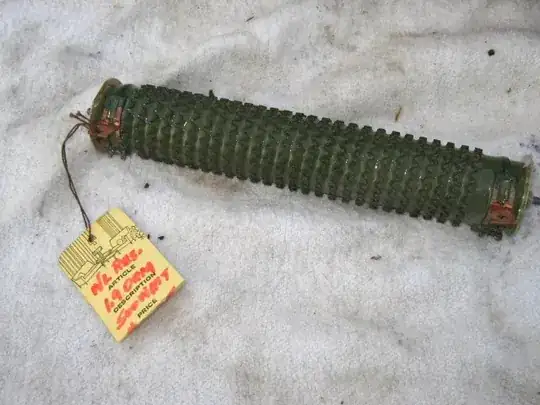
enter image description here

Just maybe.
500 Watt, 100 Ohm in this case "braking resistor".
IF you can panel mount with enough heat transfer may be OK BUT highly likely not to like long term use.

enter image description here


Just and idea: 240 V to 350V is POSSIBLY in the range that a LV DC in AC HV out inverter is happy with as it's DC HV internal bus voltage. If so you MAY be able to use a off the shelf LVDC top AC converter to produce HVAC (varying voltage) which MAY make it more able to be handled. The varying voltage may mean it is not useful.

Possible application is to drive air conditioning. 3 kW of air con is often welcome :-).
Or if you have a very very very powerful sound system ... :-) (Just joking).

enter image description here

Russell McMahon
  • 147,325
  • 18
  • 210
  • 386
  • another +1 for mentioning powerful sound system :-D – Cougar May 10 '13 at 14:55
  • +1 for actually trying to address the getting rid of kilowatts problem :-) – Anindo Ghosh May 10 '13 at 15:30
  • Get 9 more battery packs and connect them in parallel. Solves the heat problem and gives 10 times the yield! – gbarry May 10 '13 at 16:34
  • It's not clear from your write up that you understand that the power supply is NOT a 350 Vdc but is really a 10A current supply with 350V compliance. You only discuss series current regulation when in this case what is needed is current shunt regulation. You haven't addressed the OP, well actually this is Generation 5 of the OP so that could be what the issue is. – placeholder May 10 '13 at 17:18
  • @rawbrawb - I'm afraid it's unlikely that I can address your comment in a way that won't annoy - the following is not meant to be rude - just honest: I disagree with what you say completely and cannot imagine how you could not see the references throughout to either 10A, or 9A (1A for battery, 9A for shunt. | I have NOT edited my answer | There are 5 references to 10A | I arrived at the 350V figures which nobody else has mentioned by taking 1.45V/cell (NimH fully charged) x 10A x N batteries. To do that I HAD to use 10A figure. | I mention 10A semi Constant Current, ... – Russell McMahon May 10 '13 at 19:26
  • @rawbrawb ... I say "User opines that charger tries to input 10A to pack when it ought not and he wishes to reduce this to 1A." | This sentence implies 10A constant with time division between battery or load : "If battery is "happy" to receive say 10A x 10% + 0A x 90% and call it 1A mean then you can PWM a load on and off to take ALL alternator current."| And understanding of 10A CC is shown by "Best of all is if alternator is happy to be shorted or nearly shorted - then eg 10A x 10V = 100 W = easy to deal with. BUT..." ... – Russell McMahon May 10 '13 at 19:29
  • @rawbrawb ... ie overall my complete post is entirely founded on the concept of sinking 9A from a 10A constant current source when battery charging is to be reduced to 1A.| I mention battery charging at C/10, I ... |. ... Agh. I really cannot see how anyone can read other than an aim to sink 90% of a 10A current source. AT one stage I did say 0-10A sink or similar - as I wa aware that what he REALLY wants is a 1A remnant for the battery and there WILL be some occasions where he does NOT get 10A, but maybe eg 8.6A or whatever. | I imagine that the system has an alternator that saturates ... – Russell McMahon May 10 '13 at 19:34
  • No worries ... And in deed you do preface the whole thing by saying " ... treat the batteries as they should ..." but it's also clear the OP isn't/wasn't/can't be clear on what is going on exactly so I keyed off of "A controllable load that draws 0-10A as required from a nominal 350 V supply is conceptually .." but I see now that focusing on that statement is somewhat unfair. – placeholder May 10 '13 at 19:36
  • @rawbrawb - ... its magnetoics at 10A but makes a voltage much higher than is usually needed so looks like a CC source. Such supplies have a trapezoidal waveform with nearly vertical sides as the sinusoids are clipped heavily by core saturation and you see the sides of the bottom of the sine waves. A while ago I designed controllers for exercise machines using a 500W custom built permanent magnet alternator. At very very very low speed you saw sine waves but these were clipped to trapezoids as above above more than say a small fraction of one rps crank speed. This is probably similar. – Russell McMahon May 10 '13 at 19:38
  • Thanks for the comprehensive analysis and solutions Russell! I've got a lot to process but I will be sure to post an update from my experimenting as i'm sure they will of interest (and hopefully useful) to other Prius/hybrid car tinkerers. – cianz May 11 '13 at 05:48
  • Off topic - Russell, I notice you live in Auckland -- i'm in Titirangi, we've probably been stuck in traffic together, me in the aforesaid Prius! Small world eh. – cianz May 11 '13 at 06:40
  • @cianz - I live and work in a 1/4 acre jungle connected via my front entrance to Te Atatu South. I try to enter the rat race only during off-peak periods if possible. 837 2999 if ever useful. email in profile, but technical stuff best in public if possible as most then benefit. – Russell McMahon May 11 '13 at 12:17
  • @cianz Hw did i work out? – Russell McMahon Apr 08 '15 at 00:14
0

Depending on the battery voltage variation while charging and the tolerance required on the 1A you may need a constant current 9A sink.

Good question.

Mho
  • 37
  • 1
  • The proposed constant current sink would need to dissipate 9A * 288V = 2592W somehow. – Nick Alexeev May 09 '13 at 03:44
  • -1, impractical answer, please re-read the question. – Anindo Ghosh May 09 '13 at 04:25
  • Following updates to this question, it looks like that might well be the answer .. – pjc50 May 09 '13 at 13:42
  • @AnindoGhosh As the question grows this looks like one solution, and not a terrible one. 2 kW resistive loads rated for 230 VAC operation can be bought in most home appliance stores. With a little playing ... R – Russell McMahon May 10 '13 at 13:33
  • @RussellMcMahon The question is an evolving swamp. The need for sinking a few KW still seems ... entertaining. – Anindo Ghosh May 10 '13 at 13:45
  • @AnindoGhosh - Aye verily :-). [A warm swamp]. Clamp alternator with S/C IF controller allows and battery does not mind 0A/10 PWM, and if battery can be diode or FET switch isolated. OR - most likely - NiCr or Constantan wire resistors at 350V/3 kW. I have a 500 Watt resistor run at ~+ 100 V (~= 20 Ohms) made from suitably thick industrial NiCr (thick enough to self support in coil in air over 100 mm+) - that could be extended to 3 kW easily enough. – Russell McMahon May 10 '13 at 14:42
  • **VOTE THIS UP** - it's correct :-) – Russell McMahon May 10 '13 at 19:38