1

In a CB Amplifier, the Base is common to both Input and Output. Why is Input applied at the Collector and Output at the Emitter?

Could it have been the opposite?

Similarly, for CC and CE amplifiers why are the chosen Input and Output terminals selected?

clabacchio
  • 13,481
  • 4
  • 40
  • 80
user23564
  • 1,139
  • 3
  • 14
  • 20
  • Possible duplicate of [NPN transistor CE or EC?](http://electronics.stackexchange.com/questions/52103/npn-transistor-ce-or-ec) This question is about why a transistor still works when wired backwards, and answers which explain how a transistor is logically symmetric, but not made to work as well when reversed. Sorry about the close vote, but I will give you an upvote. :) – Kaz May 06 '13 at 16:36
  • @Kaz I kept looking and found another [link](http://electronics.stackexchange.com/questions/29756/bjt-in-reverse-active-mode-of-operation). To confirm I understood the content correctly I'm summarizing. Using the BJT Amplifier and interchanging I/P & O/P, the amplifier will work but with a reduced _Beta_. The BJT is biased so EB is forward biased and CB is reversed biased i.e. BJT is working in Forward-active mode and not the Reverse-active mode. This is cause Emitter is more doped than the collector – user23564 May 06 '13 at 17:39
  • Do you have a circuit diagram to support your question? – jippie May 06 '13 at 20:14
  • ![Wiki CB Amplifier](http://upload.wikimedia.org/wikipedia/commons/thumb/2/29/NPN_common_base.svg/130px-NPN_common_base.svg.png). Now interchange the Vin and Vout. – user23564 May 07 '13 at 03:07
  • CB amplifiers can have lots of different topologies inside. Assuming any port is directly connected to a collector or emitter makes no sense and is quite likely to be invalid. Also, when using a CB amplifier you have to be careful not to exceed the maximum allowed power into the antenna, which I vaguely remember is something like 5 W. – Olin Lathrop Apr 02 '14 at 19:44
  • In this question, I think we can assume that CB = Common Base, not Citizens' Band – gwideman Apr 05 '14 at 22:42

1 Answers1

2

Radio Frequency amplifiers quite often use common base circuits and I believe the main reason is because "miller capacitance" does not have the same detrimental effect.

On a normal common-emitter configuration, the input is fed to the base and the output is at the collector but, internally the capacitance between collector and base acts as negative feedback and can reduce gain.

To combat this, if the base is held at a fixed potential to ground (as per in its normally biased state), and this is supplemented by decent capacitance to ground, the miller capacitance is effectively shunted to ground. The down-side is that feeding an input to the emitter requires a stronger drive voltage because the emitter input impedance is lower.

It is lower because the emitter fed input has to also "handle" collector currents as well as the little bit of emitter-to-base current normally needed for amplification.

Consider also the differential amplifier: -

enter image description here

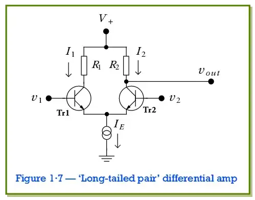
This is another circuit that uses the emitter as an input. On this occasion the input to the emitter comes from the emitter (outputting) of the other BJT. In fact, both emitters are simultaneously inputs and outputs.

Andy aka
  • 434,556
  • 28
  • 351
  • 777
  • And the second stage in a cascode is effectively a common base, for the same reason : to disconnect the miller capacitance. A cascode is effectively a semiconductor implementation of a pentode... –  May 06 '13 at 16:52
  • @BrianDrummond good call. I'd forgotten about that (which is bizarre because I've recently had to re-design one at work!!!) – Andy aka May 06 '13 at 16:58
  • In addition to the small-signal improvement in bandwidth, a cascode also improves linearity in a large signal context. I remember reading this article in Audio Magazine back in the late 70s: https://www.passdiy.com/project/amplifiers/cascode-amplifier-design – Alfred Centauri May 06 '13 at 21:35
  • 1
    @AlfredCentauri that is one of those articles that should be of biblical significance to BJT designers – Andy aka May 06 '13 at 22:15
  • You are right. Basically, the tail source keeps the current stiff, so yes, each input transistor acts as a driver for current, where the opposite transistor looks like a common base. (Which is literally true when we pin one base to the ground.) It's like they are cascoding each other. – Kaz May 06 '13 at 23:52
  • @Andyaka That article has some useful insights on cascoding. The "biblical" part comes from the religious audiophile claims: references to the bunky "transient intermodulation distortion", casting aspersions on negative feedback, suggesting that harmonic distortion and intermodulation distortion are separate phenomena, and proposing that people can actually hear phase shifts in the high frequency bands caused by rolloff in the ultrasonic region. (Come on, 10 degrees of 16 kHz is like 870 **nano** seconds.) – Kaz May 07 '13 at 00:08
  • Agree with all. Supplementing a bit more, the "problem" with the low Zin of a CB config (on the order of units of ohms, typically) is actually beneficial in some RF configs because, with the addition of a small series resistor between the emitter input and output that is driving it, Zin can be made to match Zout of its driver, and of course that is important for maximum power transfer through the CB stage and minimum reflections back to the source. Very complementary to the other characteristic of CB config which is much higher bandwidth due to C-miller shunt. So all around - good for RF ! – LateNiteOwl Nov 25 '14 at 23:02