You're charging the capacitor directly from the battery. So the charging time is related to the product RC, where R is just the internal resistance of the battery.
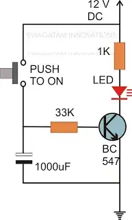
Try something like this:
simulate this circuit – Schematic created using CircuitLab
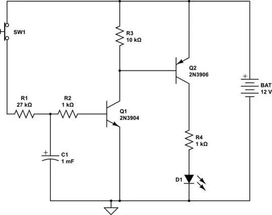
Here, I have split the base resistance so that the capacitor is charged through a large portion of it.
This not only achieves the goal of slowing down the charging of the resistor, but it has another side benefit. When the switch is released, C1 discharges into the base of the transistor through only a 1K resistance, resulting in a discharge which is much faster than the charge. We can't make that resistor too small, because we need to protect the transistor's BE junction from the discharge current.
In simulation, the LED current starts to build at around 1.5 seconds and reaches a maximum at around 1.8. So that is not a sudden turn-on, obviously. But the turn-on increases with faster delays.
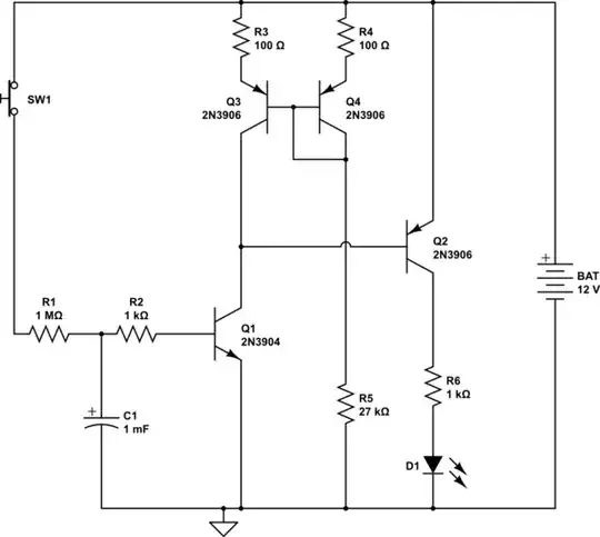
For a faster turn on, we need to add another transistor stage. The following circuit has a similar time delay to the above one, but the LED current ramps up more quickly, over a spread of 70 ms or so.
simulate this circuit
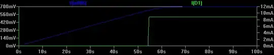
For longer times with fast turn-on, we need more gain. One way to do that is to replace the load resistor with an active load. According to an LTSpice simulation of this circuit, it generates a 55s delay, at which point the LED ramps up over an interval of about a quarter second. This graph shows the charging of the capacitor (blue) versus LED current (green):
However, it is getting more complicated than some IC based solutions. This approach is good for gratifying the hobbyist ego. ("I did it with discrete components, none of these easy to use op-amp or timer IC's, and look, there is even a current mirror and stuff!").
simulate this circuit
Can we make some small changes so that we don't need the huge charging resistor, and can use a smaller capacitor? Yes! Here is one way. We can raise the transitor Q1 so that there is a higher turn-on voltage at the base, by putting a Zener diode in the emitter, say 8.2V. Then a 100K charging resistor, and a 470uF capacitor give us a bit over a minute. By raising the voltage that the capacitor must develop, we can obtain a larger delay for the same RC values.
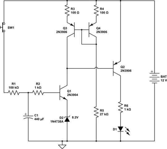
simulate this circuit