2

I have a pulse width modulation (PWM) control board that uses a 0-5V input via a potentiometer to control a DC motor speed. As I understand how this works, the potentiometer goes from 0% PWM at 0V to 100% PWM at 5V. I want to use a pressure sensor that outputs .5VDC at 0 PSI to 4.5VDC at 100 PSI to control the DC motor. Specifically, the controller will need to be at 100% PWM when the pressure is 0, and 0% PWM (off) when the pressure is at 43 PSI or 2.2VDC.

I found a somewhat similar question here, How do I invert the output of this current sensor using the other side of the LM358? but the answer was not clear to me.
Randy
  • 29
  • 1
  • 2
  • So basically you want to amplify the signal from the sensor with 1.25, getting a range of 4*1.25=5V, and then shift the level to 0-5V? –  May 03 '13 at 13:08
  • Do you have to accomplish all of these with analog electronics? Is there a place for microcontrollers? – abdullah kahraman May 03 '13 at 13:14
  • Camil, If I need to shift it to 0-5V, that is fine. Abdullah, I had built a controller using an Arudino but it failed when placed in service. I've found there is no easy way to make good reliable connections to the Arudino. The PWM controller board has a better connector on it. – Randy May 03 '13 at 13:16
  • 2
    The LM358 is not the op-amp for the job. Search for a "Rail to Rail Output" op-amp, preferably one that is designed for single supply operation at 5 Volts. For the rest, the answer is already down there :-) – Anindo Ghosh May 03 '13 at 13:40

1 Answers1

5

If you had the code for the micro doing the PWM, this would be a trivial firmware change. However, it seems you don't have access to the internals of the "control board".

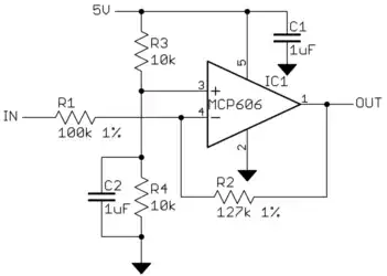
What you need therefore is a inverting amplifier. You want 500mV-4.5V to map to 5V-0V. Or put another way, you want a gain of -1.25 centered around 2.5 V. This is easy to do:

The gain is -R2/R1, which is -1.27 in this example. R3 and R4 form a voltage divider to make the 1/2 supply level around which this circuit will amplify the input. C2 attenuates supply noise on the 1/2 supply voltage.

Most rail to rail opamps would work.

Added:

Thanks to Anindo's comment, I see now the problem is really mapping 500mV-2.2V to 5V-0V.
That is a gain of -2.94 with some offset. Specifically, you want

  OUT = -2.94 * IN + 6.47

However, this circuit will essentially subtract first, then multiply by the gain. It is therefore more useful to write the same relationship as:

  OUT = -2.94 * (IN - 2.2)

That means R3 and R4 need to be adjusted to produce 2.2 V instead of 2.5 V, and R2/R1 should be about 2.94. Rounding to standard 1% values we get:

R2 = 294 kΩ 1%
R3 = 12.7 kΩ 1%
R4 = 10 kΩ 1%

Olin Lathrop
  • 310,974
  • 36
  • 428
  • 915
  • OP needs 0.5 to 2.2 Volts to map to 5V-0V, and inputs over 2.2V to leave output at zero. Just a gain change needed. – Anindo Ghosh May 03 '13 at 13:39
  • @Anindo: Fixed. – Olin Lathrop May 03 '13 at 14:03
  • Olin: Upvoted :-) – Anindo Ghosh May 03 '13 at 14:08
  • Actually, for R3 and R4, there are several combinations of 1% resistors that give zero error: R4 = 14.3K and R3 = 18.2K, R4 = 11.0K and R3 = 14.0K, R4 = 12.1K and R3 = 15.4K, R4 = 15.4K and R3 = 19.6K, R4 = 16.5K and R3 = 21.0K, R4 = 82.5K and R3 = 105K. In case you're wondering, I long ago wrote a Perl script to solve problems like this. – Dave Tweed May 03 '13 at 14:37
  • 1
    @Dave: In case someone gets the wrong impression, I just want to point out that when say "zero error", you are referring to no error due to the nominal resistor values. The error due to the 1% tolerance of the individual resistors is still there. – Olin Lathrop May 03 '13 at 15:54