1

enter image description here

I am trying to simulate an LED night light circuit using LTspice. I want to measure the voltage of C2.

enter image description here

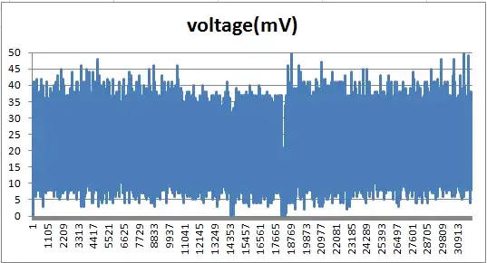
The C2 voltage is supposed to be 12 V (based on the textbook), but when I try to simulate the circuit, I only get 120 mV.

enter image description here

If I decrease the C2 value, the voltage increases, so I tried to change the C2 value to 0.47 µF but it only peaks at 5 V and decreases.

enter image description here

What am I doing wrong?

Edit: The circuit above is from my textbook and it says that I need to design an LED night circuit with 2-3 white LEDs without using transformer. The textbook explanations for the circuit is basically this.

Since I need to identify what voltage to power the LEDs, the textbook says to choose 12 V since there's a voltage drop of 8 V from the LEDs and current of 20 mA.

So to "step-down" the voltage, I can use resistor to drop the 170 V to 12 V. So the resistor has to drop 170-12 = 158 V. Using Ohm's Law, I can calculate the resistor value, 158/0.02 = 7900. But the power rating will be 158(0.02) = 3.16 W and that's a great amount of power for a night light.

So an alternative will be using a capacitor to drop the voltage with a reactance of 7900 Ohm. Using reactance formula, I got the C1 value of 0.336 µF (0.33 µF for standard value).

To convert AC to DC, I can use half wave rectifier and capacitor (C2) for filter. For the C2 value, I can use the formula from my textbook: C = I/fV I = current f = frequency V = Ripple voltage. The textbook assumes the V = 1V. So C2 = 0.02/(60)(1) = 333 µF.

winny
  • 13,064
  • 6
  • 46
  • 63
  • You probably need more LEDs and/or higher forward voltage LEDs - Try having 5 LEDs instead of 2 and see what happens – BeB00 Sep 01 '23 at 06:25
  • The circuit above is from my textbook and the textbook says that i need to use 2-3 LEDs only. I edited the post for more context. – SmartWallet3000 Sep 01 '23 at 07:46
  • please add a reference to the first schematic diagram into your question ... it is a requirement of this site – jsotola Sep 01 '23 at 15:31
  • @SmartWallet3000 The usual simplified approach is take the AC and provide a capacitor in one leg (there is a [discussion on X vs Y classified capacitors here](https://electronics.stackexchange.com/a/333049/330261) that goes beyond my specific knowledge of them) and a resistor in the other leg, leading to a bridge rectifier that is followed by a smoothing cap and a zener to regulate to about 12 V. The series LED + resistor chain would be hooked across that smoothing capacitor. Have you tried this? (Note power dissipation for each device if you do.) – periblepsis Sep 01 '23 at 18:25
  • @SmartWallet3000 There is also this [EDN article](https://www.edn.com/an-improved-offline-driver-lights-an-led-string/) on the topic for more nuanced designs. – periblepsis Sep 01 '23 at 18:28

4 Answers4

1

Your circuit is what's wrong for a couple of reasons. First, D1 blocks any return path of current after the initial charge transient, specifically, after C1 is charged - the rest of the circuit doesn't have any juice.

In first order, just to get the simulation to run properly, remove C1. You also might have to add a tiny bit of resistance (1 milliOhm sounds good) in series with your voltage source for simulation convergence. Although, I haven't used LTspice in a while and this resistor may not be necessary.

Depending on exactly what you are trying to do (product development, academic only, ect.) you have a few options to do this circuit properly.

If you have many LED's in series such that the sum of their voltage drops are getting close to that your source voltage, this approach isn't bad as most of the power will be burned up in the LED's and not the resistor. C2 isn't even necessary for operation but it can help remove 60Hz flicker. But it looks like you are only using 2 LED's. The implication here is that your circuit will be terribly inefficient and you're going to need a large resistor to drop all the volts the LED's aren't using. We can do better.

You can exploit reactance of the capacitor to get by with a much smaller resistor. Put D1 across both LED's (reverse biased). Put C1 in series with R1 and use this RC to feed the diode and LED arrangement - D1 used here provides a return path for the opposite polarity of the AC cycle. Pro tip: put the LED's back-to-back. This eliminates the need for the rectifier as both LED's provide a complementary return path for the other.

Of course we can enhance the circuit (and increase part count) by running the RC into a bridge rectifier, filtering, and pre-regulate the voltage with a Zener. But those enhancements are beyond the scope your question.

In practice, this is mains operated and would need a suitable encloser (the whole circuit is at mains potential assuming no isolation transformer) for safety and possibly a fuse to meet compliance. For only a simulation, the worst that could happen is you display a bad bode plot.

MOSFET
  • 56
  • 3
  • 1
    While it is true that the circuit as written wont work, the way to fix that is to add a diode between neutral and C1, to provide a return path for current through the capacitor. Since the capacitor is what limits the current, this circuit actually doesn't waste that much power. The problem with putting the LEDs back to back is that they are probably the most expensive part of the circuit - if you want more light, it would be better to add two more diodes for full bridge rather than more LEDs – BeB00 Sep 01 '23 at 18:25
  • What does the price of the components have to do with how they are wired? My suggestion eliminates what would otherwise be an unnecessary component. – MOSFET Sep 01 '23 at 19:35
  • The problem is that your suggestion results in two (expensive) LEDs that are each illuminated half the time - You could instead replace one of those LEDs with two cheap diodes, and have a single LED illuminated all the time – BeB00 Sep 01 '23 at 20:21
  • The price wasn't specified for any of the components. Also, the original asker mentioned that this was a simulation. Further, the perceived brightness of LEDs is a function of peak current, not the average current - this a physiological phenomenon. So in principle, for a give LED, the LED will be brighter if pulsed at high current, say 50mA to 100mA, for a short duty cycle. Using the half-sine waves of the AC line, you can drive the LEDs harder considering they will be on only half the time. So with proper impedance components, you can get more brightness out of two LEDs instead of one. – MOSFET Sep 03 '23 at 01:56
1

The problem is the forward voltage of the diodes. You can simplify your circuit by looking at the impedance of the C2 at the frequency you care about, which is 60Hz. At this frequency, C2 has an impedance of about 8kOhms. If you ignore C1 (since all that does is smooth the peaks), and ignore D1, then you get this circuit:

schematic

simulate this circuit – Schematic created using CircuitLab

If the forward voltage of your LEDs is only 2V, then you get 116V across C1 and R1, which gives a current of 14mA through the circuit, 2.5V across R1, and therefore 4.5V at Node 1. The D1 and C2 would only reduce this voltage.

The problem is that your diode models in spice are for different LEDs - your textbook clearly says that there is 8V across the LEDs at 20mA. Your LEDs are not dropping anywhere close to that. My guess is that the LEDs in your model are probably red LEDs - if you want to match the textbook, you need to find an LED model that drops 4V each (for a total of 8V) when 20mA is running through it.

You also have the problem that your capacitor C1 will charge up, and then not be able to allow any more current through because of D1. You can fix that by modifying the circuit like so:

schematic

simulate this circuit

BeB00
  • 5,303
  • 2
  • 18
  • 34
  • Yea, he’s using the default diode model `D` which models a very simplified PN junction silicon diode. Nothing close to an LED of any kind. – Ste Kulov Sep 01 '23 at 19:10
0

The C2 voltage is supposed to be 12 V

No, it isn't. C1 and C2 form a capacitive divider of which division ratio is set by the capacitive reactances:

$$ X_C=\frac{1}{2\pi f C} $$

If you calculate the reactance of both you'll see that 330n cap shows a reactance of almost 1400 times that 470u does. That makes the voltage across C2 about 0.12V:

$$ 170V \ \frac{1}{1400}\approx0.12V $$

And note that since C2 shows really low reactance and therefore shorting the load side (the LED and the resistors).

You have a few options here:

  • Since this is going to be a night light (i.e. no different than an indicator) you don't have to use any capacitor i.e. short C1 and remove C2. The LEDs will work as a rectifier as well and there's going to be flickering at 60 Hz, but won't be detectable by human eyes. Put a series diode (1N4007) and a large enough resistor to keep the "average" current at a few milliamps, and you're good to go.

schematic

simulate this circuit – Schematic created using CircuitLab

  • If the current is high (i.e. a few tens of milliamps) you can try transformerless power supply:

schematic

simulate this circuit

You may need to adjust the series dropper cap and the output cap for your needs.

Rohat Kılıç
  • 26,954
  • 3
  • 25
  • 67
  • I edited the post for more context. I still don't understand what makes the textbook wrong? I guess they calculated the reactance of C1 without considering C2? Am i wrong? – SmartWallet3000 Sep 01 '23 at 08:35
  • @SmartWallet3000, forget the ac reactance for the moment. The fundamental part of the circuit that is wrong is that the diode hinders all normal operation. The best you can do with analyzing that circuit is the transient analysis when the circuit first gets powered up. This analysis requires the initial conditions of the components including the phase angle in which power is first applied. I'm surprised by number of users providing solutions to a circuit that doesn't properly work in practice nor a simulation. – MOSFET Sep 01 '23 at 19:32
0

With a resistor (safety reasons) across C1 (330nF), it should be ok.
But only 4-5 V for 2 diodes and current through diodes = 1.20 mA !

enter image description here

Antonio51
  • 11,004
  • 1
  • 7
  • 20