17

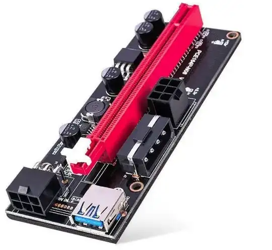
I know the title may sound provocative, but I was looking for a PCI hub, and found solutions like these:

enter image description here

I noticed that on the PCIe side, there is actually only one adapter (which looks passive) with a normal USB3.0 connector.

enter image description here

So I'm wondering, is PCIe normal USB 3.0? So, can I use a PCIe interface of a PC as a normal USB3.0?

Is it true? Is it wrong? Is this partially true?

jsotola
  • 2,497
  • 2
  • 12
  • 21
Federico Massimi
  • 735
  • 1
  • 10
  • 20
    The USB3 cables & connectors are used for convenience. Their electrical specs meet or exceed the requirements for PCIe, and they're very common & easily available. – brhans Aug 30 '23 at 12:07
  • 6
    It is always bad news to use a common convenient cable for some other application - just because someone in the future won't read the manual and plug it into whatever the connector is usually used for. – D Duck Aug 30 '23 at 12:24
  • No - BUT NVMe provides both, which may cause confusion. – pjc50 Aug 30 '23 at 15:16
  • 3
    USB cables are very cheap and that's a cheaply made product so they reused the cables even though it was not meant to be used like that. – user1850479 Aug 30 '23 at 18:59
  • The Molex iPass 74546 are intended for external PCIe cables, but as you can see from this UK distributor search https://uk.farnell.com/c/cable-wire-cable-assemblies/cable-assemblies/computer-cables?CMP=KNC-GUK-GEN-SHOPPING-PMAX-Medium_ROAS-Test990&product-range=ipass-74546 they are expensive compared to USB3 cables. – Chester Gillon Aug 30 '23 at 22:22
  • Not familiar with the details of PCIe, but does a card with a PCIe x1 connector on the PC side which expands into 4 PCIe x16 connectors make any sense? Does a PCIe expander make any sense? It thought PCIe was point-to-point (contrary to PCI where the slots where in parallel)? – jcaron Aug 30 '23 at 23:21
  • 3
    @jcaron There would have to be a [PCIe switch](https://www.broadcom.com/products/pcie-switches-bridges/pcie-switches) on the backside. The slots would be x16 wired as x1; this is fairly common in larger PCs. Another way would be passively splitting a x4 into 4 x1, this would require the upstream chipset/switch support PCIe bifurcation. Though not used here, that's commonly seen in PCIe to multi-M.2 boards used for SSDs. – user71659 Aug 30 '23 at 23:54
  • @user71659 x16 to x4x4x4x4/x8x4x4/x8x8/x4x4 is fairly common, but I don't think I've ever seen firmware support for x4 to x1x1x1x1 bifurcation – Bob Aug 31 '23 at 03:04
  • That looks to be very wrong on many levels. PCIe and USB can share the same physical interface, USB-C. That doesn't make them the same protocol. USB4 kind of muddies the waters since it wraps up a bunch of old USB protocols, the Thunderbolt protocol, and a few extra bits to make them play nice. Thunderbolt is a protocol for connecting external PCIe devices, and the physical connectors are mini-DisplayPort and USB-C. There's been other connectors used for PCIe in the past but they appear to be rare. Using USB-A for PCIe is not part of any spec, but I may be mistaken. – MacGuffin Aug 31 '23 at 05:23
  • 7
    Ah bitcoin mining gear - essentially you don't need the x16 speed for that use, but most GPUs are X16, so... they basically throw together abominations like that. Though, how that'd even work without a PLX chip eludes me. x16 slots are more common (and this cheaper) than x1 slots with the end cut for bigger cards, USB 3 has enough connectors for an x1 slot and are cheap as chips, and its gonna be a fire hazard *anyway*.... – Journeyman Geek Aug 31 '23 at 05:50
  • @pjc50: The **M.2** (NGFF) slot provides both PCIe and USB – NVMe is a software protocol on top of PCIe. – user1686 Aug 31 '23 at 09:10
  • I found a photo of the back side @JourneymanGeek and there does appear to be a PCIe switch. See my answer. – Mark Booth Aug 31 '23 at 10:44
  • @JourneymanGeek though this one has a pcie switch on it, other abominations can make do by abusing a firmware setting called port bifurcation - it will let you tell the pcie host that your x16 port is actually 16 x1 ports or some other combination. Not many motherboards support it in my experience – Bryan Sep 01 '23 at 17:44

4 Answers4

21

No they are not the same.

That adapter just uses USB connectors and USB cables for passing PCIe wiring between boards.

Justme
  • 127,425
  • 3
  • 97
  • 261
  • 5
    Also there apparently isn't a de-facto standard for the pinning, so it's important to not mix boards from different sources. Having said which, USB is being continually extended to carry additional protocols and services. – Mark Morgan Lloyd Aug 31 '23 at 06:09
11

The USB cable is just a way of making a board to board connection using cheap off the shelf components. It's electrically a PCIe lane, and completely different to USB3.

If you plug a USB device into that cable while it's plugged into the riser, there is a high likelihood that you could damage your motherboard and/or the USB device. Similarly if you you plug the cable into a normal USB port while it's plugged into the splitter board, there is a high likelihood that you could damage the splitter, the motherboard or both.

The device itself appears to be an LPE-51X "PCI-E X1 to 4PCI-E X16 Expansion Kit" and it was almost certainly designed for use cases which require very little bandwidth to the PCIe cards connected to it.

While it has four x16 slots, so you could plug in four double slot graphics cards into them, each slot is are only wired for x1, and all slots share the same PCIe x1 connection to the motherboard through a PCIe switch chip on the back of the board.

LPE-51X back view

The x1 riser card appears to passively connect PCIe pins to the high speed twisted pairs on the USB connector, as Justme said.

One thing that is not mentioned in any of the product pages for the LPE-51X is the speed and/or PCIe generation supported.

The included cable is 60cm long, which is out of spec for all PCIe generations (PCIe 1.0 & 2.0 is max 53cm, while PCIe 3.0 is max 35cm), so it's likely that this device runs at PCIe 1.0 speeds (2.5GT/s or 250MB/s) and it's only the consistent quality of commodity USB Superspeed cables, rated at 5GT/s, along with the signal integrity safety margin built into the PCIe spec that allows this arrangement works at all. It's still running significantly out of spec though, and reliability of the connection is likely to be marginal. It would certainly not be a good idea to replace the 60cm cable with a longer one.

Mark Booth
  • 1,635
  • 3
  • 24
  • 45
  • 5
    Note: This works for bitcoin mining because it needs very low amounts of data transfer. Each card pretty much mines by itself and just reports if it gets a solution or not. It is completely unsuitable for AI training, for example, which needs to constantly transfer large amounts of data around between all cards and the CPU. – user253751 Aug 31 '23 at 21:38
  • 2
    JourneymanGeek already mentioned this in a comment @user253751, so I didn't think it needed mentioning, and I don't want to promote such an environmentally unfriendly pursuit anyway. As it is, no-one is seriously using a GPU to mine bitcoin these days anyway, the first ASIC miners were created over a decade ago and quickly replaced GPU's as work rates sky rocketed. Even with ASIC mining, a single bitcoin now requires around 266MWh of electricity, which in the UK would cost £130k ($168,000), and produce around 70 tons (77.7 US tons) of Co2. People mining with GPU's today, are mining altcoins. – Mark Booth Aug 31 '23 at 22:42
  • Wouldn't RJ45 connectors on cat5e/cat6 STP cables make more sense? Then you could vary the length easier as well... – JoSSte Sep 01 '23 at 09:35
  • 2
    I'm not a transmission lines expert @JoSSte, but Cat5e/Cat6 cables are only specified to 100/250MHz, and even Cat6A/Cat7 cables are only 500/600MHz, so Ethernet uses PAM encoding to get more bits per transfer. In contrast, PCIe (before PCIe 6.0) and USB (pre USB4) use binary encoding, so only get one bit per transfer, and have to run at significantly higher symbol rates. – Mark Booth Sep 01 '23 at 14:54
  • 2
    @JoSSte I wouldn't honestly expect whoever designed the product to have put much thought into it. They probably knew that USB 3.0 has enough conductors to carry the PCIe lanes they needed, they just created cable and PCBs and tested to see if it worked. – bracco23 Sep 01 '23 at 15:51
  • 1
    So basically, the answer is that the device in the OP abuses the USB standard by employing the standard connector in an incompatible circuit. – Ruslan Sep 02 '23 at 09:03
  • @bracco23 but USB-A to USB-A cables aren't exactly standard?? – JoSSte Sep 02 '23 at 14:14
6

Is PCIe normal USB 3.0? So, can I use a PCIe interface of a PC as a normal USB 3.0?

In this particular case, no. As others have explained, USB 3.0 cables are only used as convenient high-speed transmission lines for PCIe signals, since USB cables are one of the most common and cheapest cables suitable for high-speed signaling in existence due to USB's popularity in customer electronics.


However, there are indeed a lot of commonalities between the physical layers of USB 3.0 and PCIe.

In USB 2.0 high-speed signaling (480 Mbps), a custom non-standard design was adopted. Electrically it uses LVDS-like signaling, but it's not really compatible with any other LVDS transceivers. Rather than using a pure differential design, it contains both single-ended and differential signals. The signaling is half-duplex over only a single differential pair, further complicating the transceiver design due to the need of bus arbitration. As a result, transparent USB repeaters, common-mode filters, and galvanic isolators are difficult to implement in USB 2.0.

After these problems were recognized, USB 3.0 signaling took a standardized approach better aligned with industry practices. It features:

  1. Full-duplex RX and TX over two pairs of unidirectional differential pairs.
  2. AC coupled, 8b/10b encoding for DC balancing.
  3. Current-Mode Logic.

This type of signal is commonly found in almost all high-speed digital systems, including USB 3 and PCIe, many standard hardware interfaces and transceivers exist. Thus, for the sake of following the de-facto industrial standards, USB 3.0's physical layer is largely based on PCIe. For example, the text on 8b/10b encoding in the USB 3.0's specification is identical to PCIe's down to the wordings. Some concepts in the protocol even have the same name - the Link Training and Status State Machine exists in both PCIe and USB 3.

The use of standard high-speed signaling schemes by USB 3 allows ASIC designers to reuse the PCIe transceiver circuitry in some case. For example, Intel's PIPE (The PHY Interface for the PCI Express) architecture is a transceiver capable of transmitting PCIe, USB 3, SATA and DisplayPort at the same time.

In fact, USB 3 signals are "standard" enough that you can transmit it over fiber optics by running the differential pair directly into an unmodified SFP+ 10 Gigabit Ethernet transceiver, due to the fact that SFP+ transceivers are protocol-agnostic electrical-to-optical converters that accept an arbitrary CML signal. Without doing anything else, the result you'd get is 80% functional (proper power management is a challenge).

On the other hand, there are some important differences.

  1. To be backward-compatible, all USB 3 devices are required to have a separate USB 2 transceiver, which hasn't changed. Thus, all USB 3 hosts, hubs, devices and ports are in fact two ports: a USB 2 port and a USB 3 port glued together, running on separate data lines. When operating in USB 2 mode, the device cannot benefit from USB 3's improvements. None of the described similarities apply to USB 2.0, or a USB 3 device in USB 2 mode.

  2. USB 3 and PCIe use different protocols above the physical layer, the controller and software involved are entirely different. It's not possible to speak USB over PCIe, unless you've implemented a real USB 3 controller (Or unless we're talking about USB 4, with Thunderbolt-like PCIe tunneling support).

  3. USB 3 uses Low-Frequency Periodic Signaling (LFPS) for link establishment and power management. This is a custom out-of-band signaling system that doesn't exist in PCIe and many other high-speed protocols.

  4. USB 3.1, USB 3.2, and USB 4 introduced many extensions, including multi-lane operation in USB 3.2 Gen 2x2, so its similarity to PCIe at the physical layer is not as similar as it was in the USB 3.0 days.
比尔盖子
  • 6,064
  • 2
  • 24
  • 51
  • USB 3 signaling is an add-on to USB 2 so it has all the same "problems" as USB 2. It uses the D+/D- pair like usual, then negotiates to send high speed data through the extra pairs. – user253751 Aug 31 '23 at 21:42
  • In contrast, the LPE-51X just assumes that the signal integrity will be good enough at 5GT/s, and as long as you don't replace the included 60cm with a longer one, it will probably work well enough that you don't get any obvious problems (PCIe 3.0 is max 35cm, while PCIe 1.0 & 2.0 is max 53cm). – Mark Booth Aug 31 '23 at 22:49
  • 3
    @user253751 It's the other way around. A USB 3 device attempts to negotiate via SSTX/SSRX, and only falls back to D+/D- when they're unavailable. It's possible to get a functional USB 3 link on a USB 3 port without USB 2 data lines. This hack is obviously a gross violation of the spec, but may find uses in some specialized scenarios, such as the SFP+ optical fiber trick I mentioned (as long as you don't need USB 2 compatibility, or if you can find VIA Labs's VL671 chip, which transparently emulates USB 2 on top of USB 3, another thing forbidden by the USB spec). – 比尔盖子 Sep 01 '23 at 07:47
1

A variation on the specific PCI hub listed in the question have used is a SSU-TECH SU_EUX4042.V2 PCIe card. This contains a PCIe Gen2 Packet Switch ASM1806 with four x1 PCIe 2.0 downstream ports, each with a USB3 connector (from ebay https://www.ebay.co.uk/itm/166101917681):

enter image description here

And multiple individual risers, each with a x16 PCIe connector with their own power supply connector, and a USB3 connector for a 1x PCIe connection to a downstream port of the ASM1806 (from ebay https://www.ebay.co.uk/itm/134459556140): enter image description here

I did find the while a PCIe card fitted to riser worked after the PC was booted, sometimes after about an hour the PCIe card would no longer work, in that reads returned all ones. Once that had happened sudo lspci -vvv reported that the FatalErr+ flag was set on the corresponding ASM1806 downstream port. Not sure if running PCIe over USB3 cables has signal integrity issues, or there is a design issue on this particular product.

Chester Gillon
  • 474
  • 3
  • 4