4

I am trying to get an electret microphone working with my Raspberry Pi Pico's ADC pin. I am trying to detect the output by passing it through a transistor.

I have a 4.5V voltage source. I split this with a voltage divider to create a 3V input for the microphone (labelled V1 on the diagram.) I then pass this point as the base of a transistor.

I set a resistor at the transistor's emitter to fix the current over the transistor. I placed a resistor at the transistor's collector which - with the current provided by the transistor - should set a voltage at the collector.

The ADC is connected to the collector.

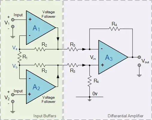
The circuit diagram is here:

enter image description here

The circuit values are:

  • R1=2.2k
  • R2=1k
  • R3=100
  • R4=220

The transistor is NPN. The emitter is connected to ground over R4.

Electret microphone datasheet.

A few things are happening which seem to indicate there's something Im misunderstanding:

  1. The voltage powering the microphone is about 0.75V. This is different to the voltage divider's output when it is independent.
  2. The output at the transistor's collector is 4.5V (source voltage.) That's not what I expected. Itcould be for the same reason as (1.)

I've tried varying all the resistors, but that didn't change (1) or (2).

I'm not sure why the electret is altering the voltage divider provided voltage from 3V to 0.75V so that leads me to the title question:

What sets the voltage drop over an electret microphone?

Input on any other issue with my design, with an explanation, would be appreciated.

Note on capacitor at Vb:

I have seen multiple diagrams online showing a capacitor to remove the DC offset at Vb. I don't have a capacitor to use currently, and to my reasoning - as I am setting the ADC voltage based on the current through the transistor, which is determined by the change in voltage at Vb, this should be independent of the DC offset at Vb.

Again, if there seems to be an issue with my reasoning here, please do comment on it.

JRE
  • 67,678
  • 8
  • 104
  • 179
  • Your circuit determines it, but without knowing what is the value of all resistors and voltage at all nodes it is difficult to say. What is R3, R4, or even R1 ad R2? And Ve? Is it a PNP or NPN transistor? Which way is emitter and collector? – Justme Aug 28 '23 at 17:11
  • I have added values to the post. – user10709800 Aug 28 '23 at 17:36
  • Don't list the resistors. Add their values to the schematic you drew. This is what schematics are for. If you go shopping for a can of paint; do they give you some reference number that you have to look up on a separate chart or, do they put a true-to-life indicator on the tin? – Andy aka Aug 28 '23 at 18:38
  • @user10709800 See [this EESE answer](https://electronics.stackexchange.com/a/677469/330261) for some examples and cautions about just jumping in without being thorough in understanding how these devices work. Also, the datasheet is really what's referenced at your link, not the link itself. So look [here](https://resources.kitronik.co.uk/pdf/3310-pcb-mount-microphone-insert-datsheet.pdf) for the PDF. And at the above linked EESE answer, it appears that the datasheet show there is about the same as the one referenced here. So I think it is directly applicable here. – periblepsis Aug 29 '23 at 01:14
  • @user10709800 Note that the answer I gave there doesn't give a complete solution for connecting up to an MCU (and it uses a 9V battery to power the electret, as well.) It stops short of a full solution as there are likely more amplification stages required to mate up with an ADC. To perform what remains specifications are needed. Also, you are better off directly using the 4.5 V source than creating a divided-down system. More initial gain that way, though you may want to waste some of the overhead with a local supply rail filter, granted. – periblepsis Aug 29 '23 at 01:28
  • @user10709800 As far as why you see 0.75 V, I'd recommend removing the electret from your circuit but keeping all the rest (BJT, etc.) Then measure again. Tell us what you see. You might also separately power the electret directly from the 4.5 V using a 1k resistor (as the datasheet says) and measure the electret voltage and report that value, too. Do some diagnostics. – periblepsis Aug 29 '23 at 02:07
  • there are two separate things that need to happen here. 1. bias the transistor. 2. bias the mic capsule. When the mic is properly biassed its DC voltage will be rather close to Vcc. This is not a good bias point for the transistor. so a coupling cap is required. At the moment it seems you are trying to do both jobs with the 2 resistors and that doesn't look like it can work. – danmcb Aug 29 '23 at 12:48
  • better approach: use a single resistor to bias the mic. Connect it via a cap to the base of the transistor, which is independently biassed with either one (self-bias) or two (classic common emitter with voltage divider setting base to Vcc/2) resistors. That should work. – danmcb Aug 29 '23 at 12:51

3 Answers3

2

Some electret microphone capsules come with a preamplifier, and some don't. If your capsule does not come with a pre-amplifier, you should add one with a circuit like this

schematic

simulate this circuit – Schematic created using CircuitLab

Then, either using your electret mic with built in pre-amp, or with added preamp, add the following components.

schematic

simulate this circuit

Connect the node \$Audio\$ to the base of your transistor in your amplifier, and connect \$AudioGND\$ to the ground of your amplifier. Your final circuit should look something like this

schematic

simulate this circuit

Math Keeps Me Busy
  • 18,947
  • 3
  • 19
  • 65
  • The problem with that system is that it will possess a signal-dependent gain at Q1 (and temp-related issues.) Without NFB, AC-grounded stages like that provide high but variable gain and distort their outputs. – periblepsis Aug 29 '23 at 01:31
  • _All_ electret microphone capsules intended to be used other than as a component of a standalone microphone come with a preamplifier in the form of a JFET because the added capacitance of more than a few cm of leads would attenuate the signal too much. I have no idea what you intend C2 to do: it is an AC bypass that will engage the full hFE of Q1 for AC which only makes sense in terms of linearity and predictability if you have some other negative feedback which you don't. – user107063 Aug 29 '23 at 12:06
  • @user107063 you are correct about C2. Probably a bad idea in this case. Deleting. – Math Keeps Me Busy Aug 29 '23 at 12:22
1

Your transistor has no emitter and you have specified none of the resistors you are using.

An electret capsule has a nominal current that it will draw when the minimal operating voltage has been reached: that is due to the internal FET operating in transconductance mode where the output current more or less just depends on the gate voltage.

Typical are 0.5mA of operating current and a specified minimum voltage somewhere between 1.1V and 2V. With larger voltages, the current will be just about the same, with smaller voltages, the FET gets into non-linear regions where the gate voltage increasingly determines conductance instead of current.

The capsule tends to operate down to very small voltages; it just delivers small signals then and has non-linear response.

Since signal and operating voltage are shared, you'd put a low LSR capacitor (22uF or so) at the point where you write VI and connect that smoothed voltage source then with a 2.2kOhm resistor (typical load/feed for electret capsules) to Vb.

You probably don't need R1: no electret condenser capsule I know would mind 4.5V. R2 can be 470ohms or so if it is just used for keeping the charge on the capacitor providing the smoothed voltage supply for the capsule. If it is lower, you get a higher operating voltage for the capsule but you may want to increase the capacitor then to keep voltage fluctuations on the DC rail from becoming audible.

There are better single-transistor amplifiers for electret microphones and I would actually check whether you don't already get sufficient signal by not using a transistor at all but directly going into VADC from Vb.

user107063
  • 2,507
  • 1
  • 13
1

You should use the circuit on the mic datasheet but increase its 1k resistor to 4.7k which will quadruple the tiny level of the output signal.

Your transistor has signal loss instead of gain so the signal output level will be very low. its voltage gain should be 100 times or more. electret mic again

Audioguru
  • 3,894
  • 5
  • 8
  • 1
    I agree with what you wrote so far. In the link I provided above in a comment I also use a 9V battery supply and a 10k resistor for the same electret datasheet specs. The 1k is in fact too low! The missing piece for the OP is the "rest of the story." [This link](https://sound-au.com/articles/mic-electret.htm) provides some good stuff to read on the topic, including a pre-amplifier stage to use to boost the signal initially by about 4X. There will need to be more to get to the ADC, though. As you say, a couple of orders of magnitude of gain, thereabouts, plus some offset for the ADC input. – periblepsis Aug 29 '23 at 01:40