Is there any transform that relates four resistors meeting at a central node
simulate this circuit – Schematic created using CircuitLab
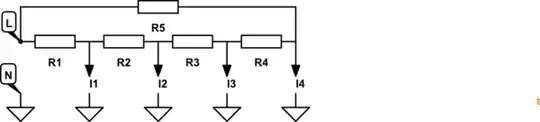
to a set of two Y resistors networks as shown below
Is there any transform that relates four resistors meeting at a central node
simulate this circuit – Schematic created using CircuitLab
to a set of two Y resistors networks as shown below
It can easily be seen that the two circuits are NOT equivalent. Label the upper left hand corner 1, and the lower right hand corner 3. Leave the other corners open-circuit. The resistance from 1 to 3 in the upper diagram is 200 \$\Omega\$. The resistance from 1 to 3 in the lower diagram is 300 \$\Omega\$.
Furthermore, this cannot be fixed by changing the resistor values in the lower diagram. Label the upper right corner as 2. The resistance between 1 and 2 in the upper diagram is 200 \$\Omega\$. Which is the same as the resistance in the lower diagram. Changing the values of the resistors in the lower diagram will upset this equality.
Or, put another way, the values of resistances that make the lower diagram equivalent to the upper diagram is for R3 to equal 0, and the remaining resistors to equal 100 \$\Omega\$. Since R3 is equal to 0 in the lower diagram, it is trivially the same as the upper diagram.
Let's call the outer points P1 ... P4 (from top-left clockwise).
In the first circuit, if you apply a voltage between P1 and P3, then it works as a voltage divider composed of R1 and R3, and both P2 and P4 will see the same voltage.
If you do the same with the second circuit, you get a 3-element voltage divider composed of R1, R3, and R4. Now P2 and P4 are located at different steps of the divider, and only get the same voltage if R3 is zero - meaning that you effectively have the same circuit as before.
the obvious answer is
R1'=R1
R2'=R2
R3'=0
R4'=R3
R5'=R4
where Rn' is the second circuit and Rnis thew first corcuit
That is just use 0 ohms for the resistor the connects the upper and lower halves.
There is no transformation that converts back the other way (unless R3'=0).
Or in pictures:
simulate this circuit – Schematic created using CircuitLab