0

I was looking at one of the schematics of the filament board of an x-ray machine, where they had used the SG3524N for the generation of PWM and MOSFETs for the generation of an alternating voltage for the filament transformer. The filament transformer in turn then creates the filament current in the tube.

  1. I am not able to understand what waves are generated by the SG3524N even after going through the datasheets since most of the diagrams there have shorted the two emitters and collectors before the use shown below.
enter image description here 2) Are the four waves produced have some phase shift? How does this IC basically work meaning how the outputs are generated in this case? I've gone through its datasheet but am not able to understand it's working the way shown here below where its outputs are given to the transistor and then to the MOSFETs:
enter image description here

enter image description here

Verbal Kint
  • 20,420
  • 1
  • 16
  • 50
kam1212
  • 404
  • 8
  • 3
    This controller was originally designed for double-ended converters, meaning it drives two bipolar transistors that it turns on/off alternatively. A typical example is that of Fig. 10-9 in the data-sheet you referred to, with a push-pull converter. Each output has a maximum duty ratio of 50% so you see how it could limit the drive in a single-ended application like in a flyback converter. For this reason, designers connect the two collectors together and the emitter duty ratio voltages can approach 90% duty ratio. – Verbal Kint Aug 28 '23 at 06:33
  • @VerbalKint how does this IC help in generating a square wave in my circuit? There are some transistors as well before the MOSFETs, I am not able to get a propper idea as I am not able to get a propper simulation through any software. Could you help me explain the use in my circuit? – kam1212 Aug 28 '23 at 17:45
  • @VerbalKint I guess in this case they have used the IC as a full bridge converter instead of a push-pull converter which requires two mosfets and is done using a center taped transformer. – kam1212 Aug 28 '23 at 18:03
  • It looks like the circuit diagram that you have shown will not going to work. – G36 Aug 28 '23 at 18:12
  • @G36 why wount it work? Could you explain that? – kam1212 Aug 28 '23 at 18:16
  • 1
    It looks like Q3 is the wrong type it should be NPN, not PNP. And Q4 should be PNP instead of NPN. – G36 Aug 28 '23 at 19:05
  • yes I also feel the same but the actual circuit works using this diagram. – kam1212 Aug 28 '23 at 19:19
  • @G36, thankyou noticing the error, there was an error in the schematic and Q3,Q4 had to be interchanged. – kam1212 Aug 29 '23 at 08:19
  • I'm glad that I could help. Did you manage to understand what wave is generated by the SG3524N? – G36 Aug 29 '23 at 14:02
  • @G36 Yes it's basically generating a variating duty cycle square wave. – kam1212 Aug 29 '23 at 15:33

1 Answers1

4

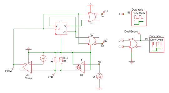
This circuit was originally designed for dual-ended converters, like push-pull or 2-switch forward types for instance. For this reason, each output is limited to 50% as a maximum value and the data-sheet states 45% as a minimum. The SG1524 was the first PWM controller designed by Bob Mammano, at the time with Silicon-General that he co-founded. The logic outputs are buffered by bipolar transistors that can be wired in common-collector or common-emitter modes if one needs inversion. A simplified internal circuit is shown below:

enter image description here

The D-flip-flop is controlled by the PWM clock (the output of the pulse-width modulator) and its outputs deliver 50% square-waves with a frequency divided by two. Then a couple of OR gates combine the PWM signal with the flip-flop outputs and produce the driving signals. These outputs deliver a duty ratio from almost 0 to 50% as a maximum.

Then, if one needs a duty ratio exceeding 50%, as with a flyback or a buck converter, then it is possible to OR the outputs as shown in the data-sheet. When you do it, you enjoy a duty ratio approaching 100%:

enter image description here

You will find a working example of a push-pull converter and many more from my free ready-made templates, running, for most of them, with the demo version Elements.

Verbal Kint
  • 20,420
  • 1
  • 16
  • 50
  • This means the two/four outputs I receive will be phase-shifted. The other two will be the complements of these phase-shifted waves right And the duty cycle will change according to my reference, and I have to use an external reference on EA+ for that, in the circuit I used above, since my IN- and comp are shorted or no reference is set on the EA-. Am I right? – kam1212 Aug 28 '23 at 15:48
  • I'm not sure I understand what you mean: you could see the two separate outputs in my simulation as interleaved if you wish, this is a classic for push-pull control for instance. – Verbal Kint Aug 28 '23 at 15:59