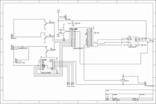
I have this schematic:
 Source: https://drive.google.com/file/d/1CbRIJQbl0sYk1aCY0UPvfPe7hDIebd2M/view?usp=sharing
I use it for a DIY colorimeter using to tricolor RGB LED with a common cathode. I'm using a BPW34 photodiode as sensor. The LEDs R, G and B are turned on individually every 45 ms each, where the LED is turned on for 45 ms then a reading from A1 happens. I have a NEMA 17 connected to the stepper motor driver as shown in the schematics. The stepper motor is used to inject liquid into the cuvette. I have an external 12 V power supply that goes into "VMOT" on the stepper motor driver.
The digital potentiometer goes up to 100 kΩ.
The only issue is that the dark current is about 20-30 when reading on pin A1. Decreasing/increasing the resistance on the digital potentiometer does not alter the reading on pin A1. The LEDs are of course turned off. There is no light at all reaching the photodiode. Is it something about the circuit?
The circuit is working fine - other than the above mentioned problem. The signal I'm reading from pin A1 is with 0.2% variation, which seems satisfactory? Do you have any suggestions for the schematic? Do I need other capacitance values? Is there something missing like resistors, capacitors etc.?