 I've been dabbling in laptop repair for a bit and at least for non-USB-PD laptops it always seems to be the same setup. Some inrush limiter coils, maybe a diode, smoothing capacitors and two MOSFETs controlled by the BQ chip. I don't understand why there are two MOSFETs used in series. Why isn't one MOSFET enough? What am I missing here?
- 31
- 2
-
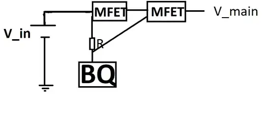
1Where and how they are in series? In the battery protection/disconnect section? Can you please draw a schematic. – Justme Aug 17 '23 at 09:46
-
2You are probably talking about back-to-back connected series MOSFETs. This configuration is a bi-directional switch that allows current flow in only one direction. You don't want the battery to discharge through the input socket, do you? – Rohat Kılıç Aug 17 '23 at 10:20
-
Added a basic schematic. Those mosfets sit directly behind the laptop charger connector. – Peter Panda Aug 17 '23 at 10:32
-
No I'd much prefer my battery being used to supply the laptop :). Thanks a lot, I was so focused on what happens to the electricity when I plug the charger, that I forgot about the battery. – Peter Panda Aug 17 '23 at 10:35
-
With the term "MOSFET back-to-back configuration" you can find much better schematics with the mosfet body diodes added. Those make the function much more obvious compared to my crude drawing. For example [here in the forum](https://electronics.stackexchange.com/questions/587035/mosfet-back-to-back-configuration) – Peter Panda Aug 17 '23 at 10:55
1 Answers
The reason there's two back to back mosfets in a battery management circuits like you described in the question is to in to independently control charging and discharging of the battery. One important detail that seems like your missing is that mosfets have a body diode. D1 and D2 represent the body diodes of the mosfets.
The first image shows the scenario where the battery has fully discharged. The BMS IC will determine what is considered fully discharged. This configuration allows the battery to only be charged. Since Q1 is off, the body diode of Q1 prevents current from flowing from the battery to the load. This only allows current to flow from the charging source to the battery.
The second image shows the scenario where the battery is fully charged. Again the BMS IC is what will determine what is considered fully charged. This configuration only allows the battery to be discharged. Since Q2 is turned off, the body diode only allows current to flow from the battery to the load.
There's also two additional states the BMS can be in which is both Q1 and Q2 are both on and Q1 and Q2 are both off. When both mosfets are on the battery state of charge is between the minimum and maximum state of charge determined by the BMS. When both mosfets are off, this would likely be due to a fault protection or system shutdown. For example if the temperature of the battery was too high, the BMS may shut off both mosfets to prevent both charging and discharging until the battery temperature falls back to the desired operating range. Another common fault protection is if there's an overcurrent event.
- 949
- 4
- 17

