6

Can someone please clarify how a PLL works and how it can the result is used to deduce phase?

enter image description here

My understanding is that a PLL is used to demodulate in situations when the demodulator knows the carrier frequency but does not know the phase.

The expression of e(t) can be computed by

1)$$ e(t) = u(t)S_i $$ 2)$$ u(t) = v(t)S_i $$

where

3)$$ v(t) = \sin f(t) $$

4)$$ f(t) = \int_0^t ( \omega _ c + c e(\tau) ) dt = \omega _ c + \int_0^t c e(\tau) dt = \omega _ c t + \theta (t) $$

5)$$ u(t) = \cos ( ( \omega _c + \Delta \omega )t + \phi ) \sin ( (\omega _ c t + \theta (t) )) $$

6)$$ u(t) = \frac{1}{2} \left( \sin ( (2 \omega _ c + \Delta \omega )t + \phi + \theta (t) ) + \sin ( \theta (t) - \phi - \Delta \omega t ) \right) $$

It's clear that passing u(t) through the LPF will give

7)$$ e = \sin ( \theta (t) - \phi - \Delta \omega t ) $$

8)$$ \Rightarrow \theta (t) = c \int_0^t \sin ( \theta (\tau) - \phi - \Delta \omega \tau ) d \tau $$

Which seems like an impossible integral to compute.The question now becomes, how does this help us determine phase? we have transformed a function of phase.

I have seen plots of theta against t being plotted, such as the one below which was supposedly plotted with the parameters as

9)$$ \omega _c = 2 \pi 1250 ,\hspace{2mm} \Delta \omega = 2 \pi 0.2 ,\hspace{2mm} \phi = \frac{ \pi}{4}, \hspace{2mm} c = 10. $$

enter image description here

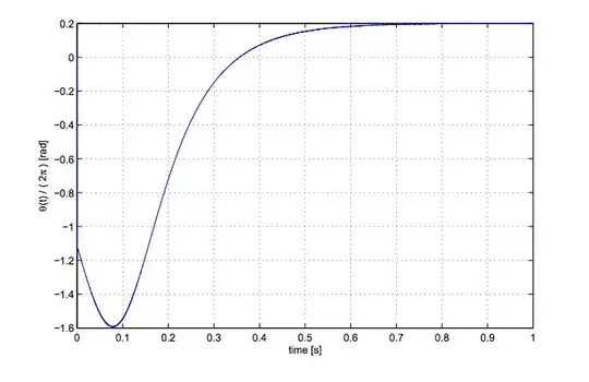
From the looks of it looks like

10)$$ \theta (t) = \Delta \omega $$

as t tends delta omega as t tends to one, which doesn't seem to make sense.Can someone shed some light on how we get the phase from a PLL, I'm really stuck on this.

placeholder
  • 29,982
  • 10
  • 63
  • 110
KillaKem
  • 1,740
  • 2
  • 13
  • 26
  • A PLL can lock on to and track a signal which is not exactly at the correct frequency (which no signal can ever be). – Kaz May 01 '13 at 22:15

3 Answers3

4

The key here is this statement "My understanding is that a PLL is used to demodulate in situations when the demodulator knows the carrier frequency but does not know the phase."

There is only one small insight that you are lacking:

Lets say we have an input waveform \$ \sin ( \omega t - \phi_1) \$ and the output from the VCO which is frequency locked but out of phase \$ \sin ( \omega t - \phi_2) \$ but in the second waveform I have a way of changing the phase (we'll ignore HOW for now) so the second waveform becomes \$ \sin ( \omega t - \phi_2 +At) \$ clearing up the second waveform expression gives us \$ \sin ( (\omega+A)t - \phi_2) \$. From this you can see that an instantaneous change in phase is actually a change in frequency. Conversely you can also express a the difference in frequencies of two waveforms as being two waveforms that are at the same frequency but one has a time varying phase.

Frequency and phase are really just two sides of the same coin. Clearly if the frequencies are far apart it doesn't make sense to talk about differing phase. Also once the frequencies are close together or even locked then it does not make sense to talk about differing frequency.

However, the modulator/LPF combination is a phase detector that behaves well (i.e. gives the right signal direction - error voltage) and allows the VCO to slew in frequency until it gets close. In short it can't know the frequency w/o knowing the phase.

A good phase detector will have a sigmoid shaped response curve. It will saturate high when the VCO frequency is way to low, it will saturate low when the VCO frequency is way too high and at some point when it is close in frequency and it makes sense to be talking about phase, then it should have a nice linear curve that is an odd function. You could view it that the curve is what changes the Modulator/LPF combo from a frequency to a phase detector.

placeholder
  • 29,982
  • 10
  • 63
  • 110
2

In general, a PLL tries to keep its VCO phase-aligned (and therefore frequency-locked) to the input signal.

If you'd like to demodulate a frequency-modulated signal, then you make sure the loop bandwidth (set by the LPF) is wider than the modulating signal, allowing the the VCO to track the incoming frequency, and then the VCO control voltage will be a replica of the original modulating signal.

On the other hand, if you want to demodulate a phase-modulated signal, then you make the loop bandwidth smaller than the modulation frequency. This forces the VCO to track only the average phase of the signal. The output of the phase detector (input to the LPF) becomes an instantaneous measure of the phase of the signal (a replica of the modulating signal) relative to the VCO phase.

Dave Tweed
  • 168,369
  • 17
  • 228
  • 393
1

Can someone please clarify how a PLL works and how it can the result is used to deduce phase?

Can someone shed some light on how we get the phase from a PLL, I'm really stuck on this.

In simple terms,

The phase detector in a PLL outputs a voltage that, on average, represents the difference in phase between the VCO output and the "unknown" input. When the unknown signal is, and remains, exactly at 90º phase angle to the VCO output, the average level from the phase detector is zero.

As the phase of the unknown signal moves away from being 90º to the VCO output, the phase detector produces a voltage that has the effect of pulling the VCO back to being nearly 90º aligned to the unknown signal. This means that the output voltage of the phase detector is capable of being used as a demodulator for frequency or phase modulated carriers.

Andy aka
  • 434,556
  • 28
  • 351
  • 777