I am having difficulties sending the correct message to the hyper terminal from ATmega32 micro controller. For some reason, the MAX232 chip is giving undesirable voltage levels. I want it to give ±15 volts at the outputs. (Pin 14 and Pin 15). Using the virtual terminal I want to achieve the following result:
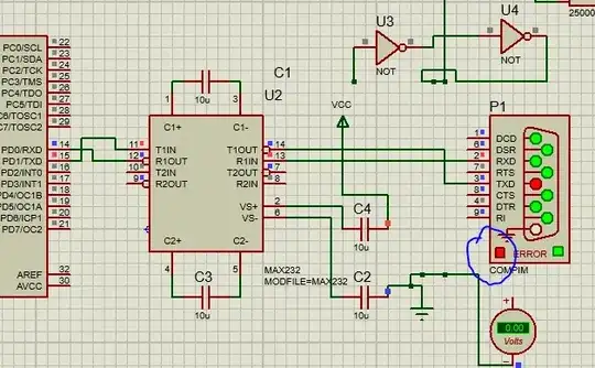
But I don't get the correct output with the following setup:
However, When I switch up pins 14 and 13 and place them at pins 3 and 2 instead, I get the correct voltage levels BUT there is obviously an error because they are connected incorrectly.
I get some weird message in the hyper terminal though despite this error as the picture below shows:
But Why won't the correct wiring i.e. where pin 14 (of the MAX232) connects to pin 2 and pin 13 to pin 3 work? Is it the capacitance values? Maybe my baud rate calculations are off? I tried using an op-amp to assist me with this problem and some NOT gates to no avail. Any advice?


