10

I want to drive a strip of LEDs from a microcontroller using PWM to control the brightness. The strip I have takes about 1.5A at 12V. I'm only familiar with purely low power digital electronics so wanted to check if these assumptions are correct and get any advice :-

  • If I use an NPN transistor to drive this, the transistor when turned on will drop about 0.7v so will dissipate over 1Watt when turned on.
  • This would require a reasonably chunky transistor and a heat sink which I want to avoid if possible.
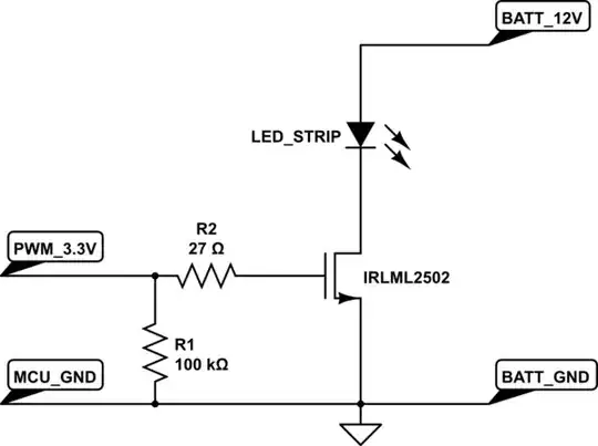
  • So I'd be better using a mosfet that has much lower resistance so I might be able to get away with a smaller one and perhaps no heatsink?

  • However looking at the spec of the various MOSFETs I can buy it looks like any that can pass this amount of current require considerably more than 3.3v I can get from my microcontroller to turn on fully.

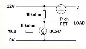
  • So am I best to have a small NPN transistor switching 12v to the input of a mosfet to control the actual LED strip? (Sorry I can't draw a diagram on this computer but can add one later if needed)

Are my assumptions correct, and does anyone have any advice or a better way? I'd also be interested in recommendations for suitable parts although that's not my main question.

(Edit: I looked for other posts that answered this and didn't find anything that was quite what I wanted, if someone has a link to a duplicate then please post it and I'll happily close the question).

John Burton
  • 2,086
  • 4
  • 23
  • 34

2 Answers2

10

For 1.5 A at 12 Volts, switched by 3.3 Volts, here is a MOSFET solution that would work well. The MOSFET suggested here is an IRLML2502 available from eBay and other sites for as little as $2.35 for 10 with free shipping.

schematic

simulate this circuit – Schematic created using CircuitLab

The IRLML2502 has a maximum on-resistance of 0.08 Ohms at 2.5 Volts gate voltage, and less as the gate voltage gets closer to 3.3 Volts. It can withstand 20 Volts Drain to Source, so it will work well with a 12 Volt supply. Drain-Source current rating is greater than 3 Amperes, providing over 100% margin of safety.

At 0.08 Ohms and 1.5 Amperes, the MOSFET will dissipate 180 milliWatt when fully on. Even allowing for the switching edges of the PWM, dissipation will not exceed 250 mW or so, hence no heat sink is required for this application.

Regarding the assumptions:

  • NPN transistor drop and dissipation are correct, give or take a bit due to Vce of specific transistors
  • Chunky transistor (BJT), not really, but a TO-220 size would be typical, and yes, a heat sink would be required
  • Yes, see suggested MOSFET above
  • Not correct, there are several low-cost MOSFETs that turn on solidly well below 3.3 Volts, and can easily pass 1.5 Amperes
  • No, with an NPN BJT there is always a balancing act around base current etc. MOSFETs being voltage driven devices, work with less fuss

Some of your assumptions are correct. This answer provides one better way, and I am sure there are others.

Anindo Ghosh
  • 50,188
  • 8
  • 103
  • 200
  • Thank you, this is very helpful and I'll look up the spec of that device, I failed to find anything like that myself so this is very helpful. – John Burton May 01 '13 at 12:24
  • The device specifications are in the datasheet linked in the answer above, happy to have been of help. – Anindo Ghosh May 01 '13 at 12:55
  • The IRLML2502 is a good suggestion, but your circuit is not. You can drive that FET with 3.3 V on the gate, but you don't want to go lower. Your R2 and R1 form a voltage divider that severly reduces the gate drive. in this case, replace R2 with a short and lose R1 altogether, basically drive the gate directly from a digital CMOS output. Put a 10 kOhm pulldown on the gate if you want to make sure it wakes up off. That way it won't interfere with normal operation. – Olin Lathrop May 01 '13 at 12:57
  • Thank you @OlinLathrop. I guess I want the pulldown for safety as it looks like half turning on the device by accident would make it overheat very quickly... – John Burton May 01 '13 at 13:02
  • @John: You can use a pulldown if you want, but don't put it on the gate side of any series resistance since that will attenuate the gate signal during normal operation. In this case, deliberate extra gate resistance is unnecessary anyway, so drive the gate directly from the CMOS logic output and put a weak pulldown on the line, like 10 kOhms. – Olin Lathrop May 01 '13 at 13:05
  • @OlinLathrop I understand. I'm thinking that if I accidentally define the microcontroller pin as an input it's not clear to me what the voltage will be so it's better to be safe for the cost of a resister. – John Burton May 01 '13 at 13:14
  • @OlinLathrop I have a bunch of IRLML2502 based boards which turn pretty solidly on with 2.0 to 2.4 Volts (2x NiMH, well down to depletion) on the gate. The voltage divider is (was) going to result in 3.297 Volts, which is well above the characterized minimum of 2.5 Volts Vgs from the datasheet. However, fair point on not unnecessarily applying a divider when it can be easily avoided. The gate resistor stays since I prefer not to expose an MCU pin directly to a potential gate short, but that's up to the OP. – Anindo Ghosh May 01 '13 at 13:34
  • @AnindoGhosh well, i'll take advice on what's best... – John Burton May 01 '13 at 13:42
  • @JohnBurton I would only be able to give advice colored by what paranoid-me considers safe, and what has worked for me. Olin brings a fair amount of experience to the table too, and I would take his advice in areas I am not confident in. Finally you're the one to decide for your purposes. – Anindo Ghosh May 01 '13 at 13:57
  • Its not easy for me to know. I figure that as this is just for a small home project it probably doesn't matter too much either way. I'm more likely to break it in 100 other ways by accident! Thank you for all the help and discussion, it's made me keen to actually build this now :) – John Burton May 01 '13 at 14:10
  • @Anindo: I see now that your pulldown is 100 kOhm, but somehow I saw that as 100 Ohms earlier. I agree that 100 kOhms doesn't matter. As for the 27 Ohm series resistor, I don't see it doing any harm, but there is not much point to it especially if the intent is to protect the processor from a gate short. If you have a gate short, you already have a hardware failure anyway and the board is no good. Unless you have something unusually expensive driving the gate, you're not going to diagnose it at this level and replace the FET. – Olin Lathrop May 01 '13 at 20:56
  • @OlinLathrop A 100 Ohm pulldown! I can see why that would cause shock and awe :-) – Anindo Ghosh May 02 '13 at 03:37
  • @OlinLathrop I dont understand the point of R2, given that its 27 Ohms. 3.3v/27R is 122ma which seems like a lot to draw from the data pin of an MCU. Arduinos for example have maximum current from data pins as 40ma before damage occurs. Wouldnt 180R be better assuming you have similar limitations to the arduino, you should get 3.29v and 18ma to the gate. Im still learning, so im hoping i have missed something really obvious. – hamsolo474 - Reinstate Monica Oct 16 '17 at 22:18
  • 1
    @hamsolo474 The gate to ground junction of the MOSFET is almost an infinite resistance, in that the DC current through R2 will be negligible. Perhaps you are modeling the gate junction as a short circuit. – Anindo Ghosh Nov 19 '17 at 13:24
3

First thought is this circuit: -

enter image description here

The MCU will turn on or off the BC547 (virtually any NPN will do) and this will apply (or remove) 12V to the gate of the P channel FET. You'll need a P channel fet with low on resistance. 0.1 Rds(on) will dissipate less than 0.2W so that's a good point to start hunting for the FET.

If you are switching in the 100's of hertz then 10k gate-to-source is OK for the FET but if you are in the several kHz region a 1k value would be better.

Possibly IRLML5203 is a decent choice - it has 0.098 ohms Rds(on), 30Vmax, 3Amax and is SOT23

Andy aka
  • 434,556
  • 28
  • 351
  • 777