My suggestion: slope detection.
Set up a common AC supply from an oscillator/amplifier (buffering may be desirable). For each sensor, use this circuit:
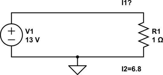
simulate this circuit – Schematic created using CircuitLab
Note that \$Z_0 = \sqrt{\frac{L}{C}}\$ is a design parameter, with \$Q = \frac{R}{Z_0}\$ giving the bandwidth of the filter. More exactly, bandwidth shall include the losses of L1 and C1, namely the parallel equivalent of R1 and the equivalent parallel loss resistance; this can be measured with a method such as this (link to my website).
Having an 11% adjustable range, implies that standard 5% components should be able to do this, perhaps with a little adjustment: if your sensor inductors can be made very repeatably (consistent geometry, equal number of turns?), this should be feasible, or an adjustment screw might be an acceptable option (depends on sensor geometry, and desired spacial sensitivity pattern).
Alternately, C1 can be adjusted, but large-value variable capacitors are expensive or unavailable, and swapping out components doesn't seem appealing. The voltage is also a bit high to use common varactors; other diodes can be used to the same end, and schottky rectifiers often have quite large junctions (high capacitance) at low cost, and offer a fair working range (i.e. over 40V reverse bias is common), so may be attractive. The frequency and impedance might also be adjusted higher, give or take limitations of emissions.
You didn't say anything at all about your sensors so I'm making the assumptions that 1. the Q factor can be high enough at some operating frequency, and 2. inductance is a free design variable (i.e. varying wire size and number of turns inversely).
In a practical matrix, you probably want as few components as possible, and multiplexing the resonant nodes themselves, to some kind of detector, which can be RCD as shown (amplitude sensitive only), or which can also be synchronous e.g. an MCU sampling in quadrature or better versus the reference clock, which can be disciplined in turn by the MCU, giving perfect timing.
Conversely, perhaps detector per sensor, or per set of sensors, is required to give enough total bandwidth to sense all of them within a sensor scan period (a refresh rate of say 20Hz would be fairly minimal for HID purposes, for example, but more or less may be required for a given application; this is undefined, so, up to you to decide how best to scan it).
A quadrature synchronous detector gives a direct vector measurement, i.e. phase and amplitude, greatly increasing sensitivity, and allowing inductance to be measured directly; an RL network could be used just as well (no capacitor needed), if enough bits per sample, or samples per cycle, are available (note this can be equivalent-time sampled, assuming a well behaved, clean sine wave with little noise pickup).
Or perhaps the oscillator is controllable, so that the resonant peak (and its width / Q) can be tracked, and the process repeated for each sensor (giving a result equivalent to a vector measurement, given a little assumption and analysis).
If one-at-a-time sensing is acceptable, then the network can be reduced to an AC current source (or voltage + resistor) into the detector, with the LC (or L alone) multiplexed via analog switch (mind that the switch's resistance and capacitance affect the result and so need to be incorporated as part of the calibration!).
As for sensor design, if this is still an open question -- I might suggest a grid pattern, preferably with cores made from vertical ferrite rods (thru / into the plane), on top of a shield/backing layer of a ferrite plate (parallel to the sensor plane, offset from it by the length of the rods). Sensor windings are looped around rows and columns of pegs, respectively (much as windings on a guitar pickup, but rather than a single set of pegs, a whole X-Y array thereof), and windings should be driven differentially (the circuit becomes slightly more complex to incorporate this symmetry) to eliminate crosstalk between each other, and to external noise sources.
Indeed, a core might not be needed at all, if the measurement is sensitive enough. Sensitive enough again, and turns might not be needed at all, a single turn might do, i.e. a straight wire along the grid. Which, is my understanding, how such plotter grids as Wacom tablets work: the grid itself is highly insensitive, but handled carefully, a scalable (\$\mathcal{O}(X+Y)\$) array is the result. The pen may also be active, whether as an RFID detector + code generator to uniquely discriminate the pen from ambient noise, or a fully active (battery powered) beacon. In any case, the relative strength of the signal between some X and Y grid positions translates to sensor position, at least in the immediate space above the plane.
