With your help on stack exchange, I finally finished assembling my first LM5143QRHARQ1-based buck converter! And it works! It does output 7V (well 7.03V) The only problem is that it consumes around 0.18A with the following setup (and no load): 15V lab power supply --> Step up converter to 43V (my regulator is designed to work with voltages from 40 to 55V) --> Buck converter to 7V.
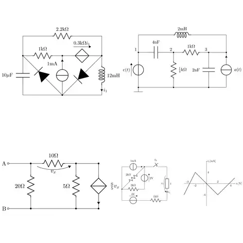
This is my Buck's schematic and this is its datasheet:

What is weird is that the current draw changes with the bench power supply voltage. With an input voltage to the boost of 13V, it consumes 0.2A, with 15V, it consumes 0.16A...
 The above is the boost converter I'm using. It's based on the TL494C from TI. With only the boost converter attached, the displayed current draw is 0A. Only when I attach my buck it rises.
I measured the temperatures and all components on the board stay below 31C (with 24C room temperature). It's also making a weird buzzing sound when it's on. I can't test it with any load today since I don't have an oscilloscope to actually see what's happening right now. So is it normal to consume so much with no load attached? Could there be a small short somewhere and I didn't notice it while assembling? 0.18A seems outrageously high to me...
Also, this is how the board looks like. It's been soldered with an MHP30 mini hot plate for the most part and just a few manual adjustments.

UPDATE
So I removed a lot of the solder blobs on the PCB and resoldered a bunch of connections. I removed the intermediary boost converter from my adjustable power supply and went with the following setup: 48V fixed AC/DC power supply --> Multimeter in series to measure current --> My buck
Measuring current, **it draws around 50mA, so power loss is 5010^(-3)48= 2.4W , a slight improvement from the 2.7W previously, but not much...
When I first soldered the board, most components would stay below 31C and it would make a noticeable buzzing sound.
After another resolder, one side (since the buck is 2-phase) of the converter had its MOSFETs higher than the other side (38C hot pair, 33C other pair). The buzzing sound was still there
After yet another resolder, now the opposite side of the buck (the other 2 mosfets) are hot now and the others at 33C. Interestingly, the buzzing sound became less noticeable. I'm sticking with this configuration
The hottest parts seems to be the schematic left side diode, nearly hitting 39C with no load attached, which is really weird and I can't quite explain why. I haven't yet tested this with a heavy load or any oscilloscope. I did test it with one of those small Arduino LEDs and it brightened it without any problems
 The encircled red area is slightly above the 30-33C of the rest of the circuit. The temperature there ranges from 34 to 39C, with the diode getting the hottest. The other identical diode is at 31C on the other side of the circuit. The main IC stays at 33C
I'm not sure what can be improved at this point or if I'm doing something wrong... 2.4W is a lot of power dissipation, and you would expect the reverse polarity protection N-channel MOSFET to be the hot guy (since power dissipation would be its RDS(on)Vin= 1.110^(-3)*48= 0.48W, but it looks like the diode is dissipating the most power? I hope I didn't damage it while soldering at high temperatures for too long, since it wasn't so hot in the previous attempts)
I also tried measuring the efficiency of the converter with that small Arduino light bulb (which consumed about 4mA) and a resistor using this tutorial page form TI and it resulted in 0.704 (70.4%), which is in the range of the IC graph?