I am working on a power supply for a stepper motor driver which requires 48 V and 12 V to operate. The 12 V rail must present all the time if it was cut off for any reason then the 48V should also be disconnected! I am feeding the 48 V to a DC-DC Buck to get the 12 V rail.
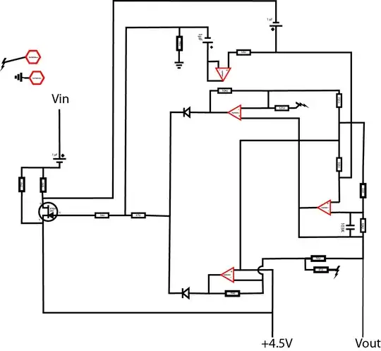
I do not want to use a mechanical relay so I came up with this circuit to disconnect the 48 V in case the 12 V output of the buck converter was shutdown for any reason.
I have noticed that it has a very slow response time, it may take up to 600 ms starting from disconnecting the 12 V till the 48 V disconnects(!) which is not accepted; I want it to be in the range of few milliseconds! I tested this circuit with 48 V and 12 V lab power supply with load up to 100 W.
So how to improve this circuit to have a faster response or maybe if it is not suitable at all, may be I should replace it with something else!
EDIT
The 48 V circuitry with the buck converter are on a sperate rail and the p-mos switch circuit will be the main entry point supply for the stepper motor driver circuit and will be fed directly from the 48 V (after reverse polarity protection and the 12 V source), so in normal conditions, the 48 V rail with the buck converter will work and supply the p-mos switch circuit with the required voltage which will supply the driver circuit but if the buck converter stopped working for any reason, the p-mos switch circuit will not work and the the driver circuit will not be supplied with the 12 V and the 48 V. The power supply circuit is still under development and is not meant to be a final product yet! so I added several components just for extra protection in the development phase!
EDIT
I found that my bench power supply is the cause for the long time response, it would take up to 500 ms to go below 0.7 V .
Now I would like to know if the the pmos switch circuit has any hidden issues with-in the current configuration or there is any other better solution .

