0

I was reading one of the patents for the x-ray generator when I found a resonance inverter attached in front of the switching circuit. I understood how the system works but one statement written is kind of confusing for me:

"The pulsation frequency of total output voltage is increased in proportion to the number of inverters".Reference: page#12

I do not understand how the number of inverters circuits affect the frequency. They are just for smoothening and nothing else as shown in the diagram 170 block from the patent: enter image description here

kam1212
  • 404
  • 8
  • look up 'polyphase converter'. N phases, if staggered in phase, produce N pulses for every pulse from a single inverter. – Neil_UK Aug 10 '23 at 07:11
  • @Neil_UK there is nothing in the diagram about polyphase converter. It's just a simple resonance inverter. – kam1212 Aug 10 '23 at 07:31
  • 1
    There's something in your question, how the number of inverters affects the pulsation frequency, that can be answered by looking up 'polyphase converters', and understanding why they are used. – Neil_UK Aug 10 '23 at 08:47

1 Answers1

2

It's a poor reflection upon the patent system that something so "obvious to those skilled in the art" gets accepted, let alone with such regularity, but alas, here we are.

It also helps to actually be skilled in the art, which, at least at a cursory reading, they weren't?

Mind, I don't particularly care to read the whole thing, so I haven't.

I did find this further down,

In addition, the anode voltage generator 110 and the cathode voltage generator 120 include feedback controllers 150 a and 150 b configured to control the multiple switching circuit 132, respectively. PWM signal which is outputted from each of the feedback controllers 150 a and 150 b may have phase difference of 180/N degrees.

It's not clear if it's simply legalese that they stipulate 180 degrees or "any angle" and allow "180/N degrees" (well, clearly "any" supersedes the rest!), when exactly one of those holds any advantage. Indeed one could further refine the claim to say, phase of each module being within 90/N of its intended angle, so that a range is still captured (i.e. you can't evade the patent claim by making a 91°-phase-interleave machine) while emphasizing the functional claim. Or maybe they couldn't get that, because that was patented decades ago (if it was at all, I don't know). It all seems so obvious that I doubt there was any consideration of "is it patentable".

Anyway.

If you cut out the inverter and resonant network and assume any abstract mostly-sinusoidal source, they're basically saying this.
schematic

simulate this circuit – Schematic created using CircuitLab

This is an acceptable simplification because, for identical inverters, resonant networks, transformers, rectifiers and filters (just replicate everything in the stack), the phase between them will be equal, regardless of waveform; and being resonant, we can assume a waveform somewhere between sine-ish and square-ish (it's not going to be some weird multi-loop squigglefest).

In this model, the sources are identical, with one flipped upside down i.e. 180 degree phase shifted. The consequence of this should already be obvious: both full-wave voltage doubler rectifiers already perform the frequency-doubling function (notice the output ripple is 2kHz, while the input is 1kHz, hence "full wave"), and if we rotate the phase of the fundamental by 180°, the 2nd harmonic gets shifted by 360°, which is to say, nothing at all.

They clearly show full-wave voltage doublers at the output, so this is apparently their claim. An anti-claim, nothing at all. Huh.

rectifier simulation

If we were to assign another phase angle instead, we might find these peaks starting to cancel out. In fact we find a minima in output ripple at 90° (because the 2nd harmonic is shifted 180° -- bingo!). And so on, as we stack more modules we can use finer phase increments to cancel out each desired harmonic.

schematic

simulate this circuit

Here, one source is set to 90° phase. Note the cancellation:
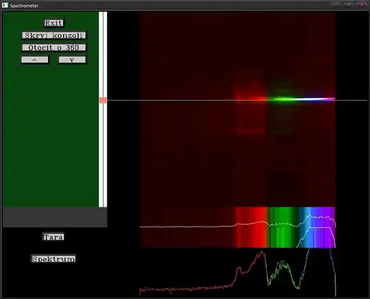
Ripple frequency doubling effect

Tim Williams
  • 22,874
  • 1
  • 20
  • 71
  • Sir do you mean to say that by the frequency they mean to say the frequency of the DC ripples shown above?? – kam1212 Aug 10 '23 at 15:25
  • 1
    @kam1212 Precisely – Tim Williams Aug 10 '23 at 15:26
  • One thing more. Why do we need ripples here instead of mking it a much better DC voltage using capacitors and propper filtering – kam1212 Aug 10 '23 at 15:27
  • 1
    How else would you propose to filter it? Consider the cost (and size, and safety!) of capacitors rated for these voltages. There is some interest in reducing the amount of capacitance required, so that the spark-discharge (fault) current is a little less catastrophic; something this high-voltage will never be human-touchable, but these voltages can easily destroy machines as well. – Tim Williams Aug 10 '23 at 15:31
  • Right. Then it means if I use two switching/inverter blocks in a single anode/cathode line then even that would change the resulting output frequency at the single anode/cathode side, without connecting the anode and cathode at this stage. Am I right? – kam1212 Aug 10 '23 at 15:55
  • I don't know what you mean "without connecting"; if you mean the output would be open-circuit, no load current means no capacitor discharge occurs, and no ripple. Under load, ripple appears, and its waveform does depend on phase shift between the modules. FYI, the tube can be treated as an adjustable constant current sink (dependent on heater temperature). – Tim Williams Aug 10 '23 at 16:02
  • I mean taking a single part ie anode only. The image shown in the question shows that there are two switching circuits ie 8 IGBTs. If the upper 4 makes a square wave and the other 4 makes a square wave of 180/90 degrees out of phase then the output voltage will still have a frequency ripples according? Without connecting the combined anode and cathode together. – kam1212 Aug 10 '23 at 16:31
  • Also, the sentence that output frequency depends on the number of inverters is also not true completely as logically it depends on the phase difference. With even two inverters we can create multiple ripples by changing the phase. Kindly tell me if this is right or wrong. – kam1212 Aug 10 '23 at 16:31
  • Each module has the regular, base (2 x Fsw) ripple at its output terminals. The only thing that's being done is superimposing them, which can cancel out one frequency when phased properly. Another way to put it is, it's always the same frequency, just with different harmonic content (in particular, the fundamental can be made low, though not eliminated in practical terms as there is always some imbalance in phase shift or module output). – Tim Williams Aug 10 '23 at 18:07