1

I need to convert a digital signal generated from a microcontroller GPIO (0-3.3V) to a high-power (15-40W) current signal to drive an LED chip for illuminance, where the signal frequency can range from 1kHz to 1MHz.

The goal is to utilize the optical channel for data transmission while fulfilling the constraints of regular illumination. Digital data will be encoded in the LED with on-off keying at a high frequency and at the same time maintain a flicker-free and stable illuminance, so the current must be very stable.

How should I design the circuit?

Will the below design using a constant current driver, a voltage-controlled SPDT work? The clock signal in the diagram is supposed to be
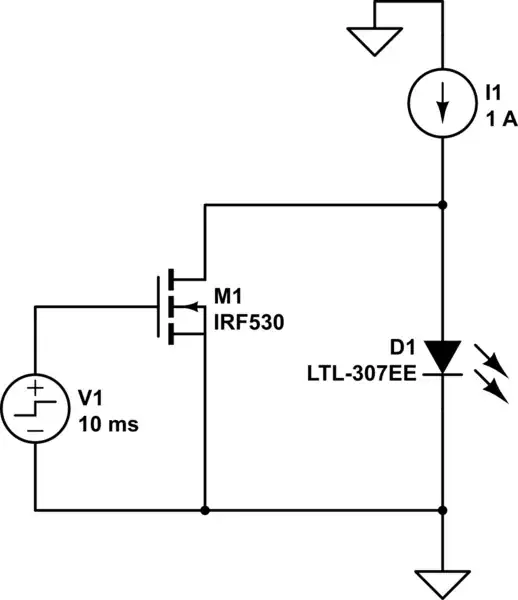
enter image description here

Null
  • 7,448
  • 17
  • 36
  • 48
hailstone
  • 41
  • 5
  • The frequency impacts the amount of data that can be piggybacked. So in general the higher the better. I put a 1MHz limit here because that's the limit on the receiver end. – hailstone Aug 09 '23 at 15:06
  • Why not say "optical data transfer" instead of illuminance? Please also supply the data sheet for the LED. – Andy aka Aug 09 '23 at 15:08
  • Both requirements are important, illuminance is like the constraint, while optical data transfer is the quantity to be optimized. Let me rephrase the question to clarify that. – hailstone Aug 09 '23 at 15:11
  • I am not absolutely sure, but I am assuming the LED chip is not the most important part here, as I would want to make the design work for a large variety of LED chips, but I will probably be using the Cree XLamp CHA0825 for this particular implementation which can be found here https://www.cree-led.com/?s=cha0825 – hailstone Aug 09 '23 at 15:15
  • @greybeard Was going to comment the same but what if you would sense only in the blue spectrum? The blue light wound shine though the phosphor and go on-off before the phosphor would react. – winny Aug 09 '23 at 15:31
  • Unfortunately, I am not aware of that. Do you mean phosphor coating will cause a problem? What would be the alternatives? I have only been checking on the rise time and fall time. – hailstone Aug 09 '23 at 15:32
  • My understanding is this works fine in the blue spectrum, up to 20MHz or so. The yellow phosphor band can simply be ignored. – Tim Williams Aug 09 '23 at 15:57
  • (In commenting on light from phosphors, I should have been more precise: light from phosphors can't be modulated usefully to anywhere near 1 MHz. I found deplorably little on spectral and temporal response of contemporary photo detectors.) – greybeard Aug 09 '23 at 16:35

1 Answers1

1

Typically this is done by shunting the LED. The current source doesn't care, of course (as long as it responds fast enough to changes in load voltage, anyway; this is not a guarantee, and depends on design), and it saves one pole off your example (as the LED doesn't need to be open-circuited when "off").

Actually, it's an improvement, not to open-circuit the LED, but to discharge it -- device capacitance and stored charge will cause it to continue glowing for some time (100s ns? µs?) if left alone, but shorting it out solves that.

schematic

simulate this circuit – Schematic created using CircuitLab

(drawn with default component types only; just showing topology)

Tim Williams
  • 22,874
  • 1
  • 20
  • 71