8

The text in section 4.1 of Designing With Opamps - Part 1 reads:

non-inverting amplifier from text

Rin is the input resistor, and is needed because an opamp needs a reference voltage at the input.

I don't see a similar resistor-to-ground in other non-inverting op-amp diagrams, and I don't see that resistor having an effect in my Falstad simulations.

Can someone explain what the author is trying to convey or what value Rin is providing?

Thanks!

pipe
  • 13,748
  • 5
  • 42
  • 72
Jeremy
  • 81
  • 1
  • 3
  • 4
    If it is left unconnected, with an high impedance op-amp, it's like an antenna. The output will likely be a 50Hz or 60Hz sine. – TEMLIB Aug 06 '23 at 12:10
  • 1
    I added the audio tag to emphasize that most things on the (excellent) ESP is about audio, this circuit included. – pipe Aug 07 '23 at 11:42

7 Answers7

16

It depends on what is connected to Vin. The resistor is required when the input is AC coupled with a capacitor, for example.

Without the resistor the DC potential at the positive input is undefined. In reality, the bias current of the positive input will probably charge (or discharge) the AC coupling capacitor.

The DC voltage of the AC coupling capacitor will slowly reach either the positive or negative rail (depending on the direction of the bias current) eventually exceeding the input common mode voltage rating of the amplifier and/or clipping the input signal.

feynman
  • 2,466
  • 3
  • 10
  • 1
    Why is the resistor required when the input is AC coupled? In the context of this question I'd like to assume that the input is AC coupled. – Jeremy Aug 05 '23 at 19:48
  • 1
    I added additional information to my answer, @Jeremy – feynman Aug 05 '23 at 20:12
10

With no input connected to Vin, the resistor biases the non-inverting input to 0 volts / GND. Imagine if this was an unused audio input of a mixing desk, without the resistor the output from the op-amp could be at any level and producing a lot of output noise.

You'd expect the output to be zero of an unused input in a mixing desk so, you need the resistor.

It isn't needed in your falsetad circuit because you have the input signal permanently connected and, that signal source provides a DC path to GND / 0 volts.

Andy aka
  • 434,556
  • 28
  • 351
  • 777
6

However, after all these comprehensive answers, a question remains, "Why do ordinary (non-op) amplifiers not need such a resistor anyway?" I will try to explain why in my answer below.

Classic biasing

In ordinary transistor amplifiers, biasing is done on the base side. For this purpose, the additional voltage/current biasing source is first connected in series/parallel to the base of the transistor and then the input voltage source is added. Thus the two input signals are summed and the amplifier never runs out of input signal. The source of the input biasing current is clearly visible and everything is clear.

Op-amp biasing

In op-amps, however, things are reversed and biasing is done on the emitter side. For this purpose, a current source is connected to the emitters of the input differential amplifier. It sets the emitter and, accordingly, the base biasing current, which for an NPN transistor must enter the base. But where should it come from? The answer is somewhat unexpected, "From the ground." And from where should it pass? An even more unexpected answer, "Through the input source." Thus the full path (loop) of the biasing current in the simplified circuit of a differential input stage below is: the positive terminal of the negative power supply V- >>> ground >>> input voltage source >>> base-emitter junction >>> emitter current source >>> the negative terminal of V-.

schematic

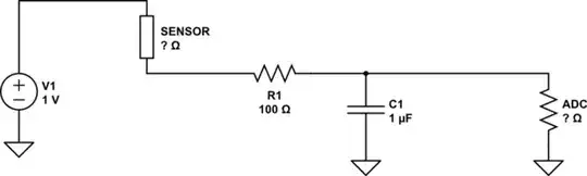
simulate this circuit – Schematic created using CircuitLab

Although for our purposes in this case it is not essential, here is some data about the schematic. At 1 mA quiescent emitter current, the base current is about 3 μA and the quiescent output voltage is about 5 V. A 1 V common-mode input voltage and a 20 mV differential input voltage are applied to the circuit; so the output voltage is about 7 V and the gain is close to 100.

Long-tailed pair Vout

Why did the circuit designers decide to resort to this non-standard solution of closing the biasing current path through the input source? The answer is obvious - in this way they achieved the maximum possible op-amp input resistance because nothing shunts the input.

Circuit fantasist
  • 13,593
  • 1
  • 17
  • 48
  • 2
    @user107063, I totally agree with you but my purpose here with this highly simplified schematic of a classic *long-tailed pair* is to show the path of the input bias current. I have found from experience that people have no idea what it is, where it comes from and why it flows there. I even thought of not drawing the right half, but the circuit becomes uncontrollable through Vin1 because the emitter voltage is not fixed. – Circuit fantasist Aug 06 '23 at 17:15
  • 1
    @user107063, I have made the emitter quiescent current more realistic... – Circuit fantasist Aug 07 '23 at 10:25
  • 1
    @user107063, OK, IMO 2 mA emitter quiescent current is fine. Then the quiescent output voltage is around 0 V. – Circuit fantasist Aug 07 '23 at 11:37
  • 2
    If you then use superbeta transistors with hFE=1000 (say), the bias current will be 1µA with a possible offset current of another 1µA. Modern precision opamps will actually provide the bias current with a separate calibrated sink on each input, meaning that unmatched impedances on the inputs don't cause offset voltages. – user107063 Aug 07 '23 at 12:18
  • 2
    @user107063, That's great... but I still want to know how it would help us with the answer. Because, as I have already said, at the stage of clarifying the principles, the details get in the way. They are for the later stage of designing… – Circuit fantasist Aug 07 '23 at 12:27
  • 1
    Illustrating the details with a circuit that doesn't work is not persuasive, and giving an example circuit without actually mentioning what kind of bias current it will actually cause is also not overly helpful. A careless look at your diagram will imagine the biasing currents to add up to 2mA when almost all of that current is actually Ic1 and Ic2. Filling in some hFE will give an actual number more in line of what you actually get to see. – user107063 Aug 07 '23 at 12:48
  • 1
    @user107063, I do not agree with the remark about the bias current because I have very clearly marked (including with arrows) all the currents - the emitter Ie, the two base Ibias1/2 and the two collector Ic1/2. It is obvious that Ibias = Ic1/*beta*. I am unpleasantly surprised that you are so focused on the details without appreciating the general idea, which is the purpose of my answer. I had a different opinion of you judging by your replies and comments... – Circuit fantasist Aug 07 '23 at 13:04
  • 1
    I conclude with the remark that such disputes are fruitless because everyone stands on their own level and speaks in their own language. They make some sense if an effort is made to understand the other point of view. – Circuit fantasist Aug 07 '23 at 13:05
4

In this particular circuit, it is not required. All it does here is that it keeps the input from floating when no signal is present and provides a DC path for the input bias currents of the op-amp to flow (which doesn't matter for this particular circuit as shown).

The price that is paid is lowering the input impedance of the circuit by a lot (10k vs the megaohms or teraohms of input impedance of the op-amp).

Transistor
  • 168,990
  • 12
  • 186
  • 385
DKNguyen
  • 54,733
  • 4
  • 67
  • 153
  • That price might not be that bad. In many high performance cases, the source or cable impedance should be matched by the amplifier input impedance. Common impedance values are as low as 600, 75, 50 ohm. The point is, do not just slam in a random Rin value, but select a proper value for maximum performance according to the requirements of your project. Examples are: avoid signal reflection, or minimize noise. – Roland Aug 07 '23 at 21:52
3

The need for Rin of course depends on what is hooked up to the "IN". And to the type of op amp.

If the signal source at IN has an internal resistance of 10 kilo ohm, for DC, then, obviously, you don't need the Rin resistor.

If the signal source is coupled in with a capacitor, and if your op amp cannot work with an input that is floating with regard to DC, then Rin might be needed.

Be aware that the internal resistance of the input signal, and Rin, will create a voltage divider. If you want to amplify the input signal with a factor of 10, and the input voltage divider divides the signal with some factor, then you will have to choose new values for R1 and R2.

Roland
  • 736
  • 5
  • 13
2

The simulation shows that the input signal source produces 5V and -5V then it is connected to ground as a DC input reference voltage that Rin would have provided. Therefore Rin is not needed: opamp

Audioguru
  • 3,894
  • 5
  • 8
  • You cannot say anything about the internal resistance (impedance) of the source if you only know the voltage. You also need to measure the current, and use Ohm's law. There could be capacitive coupling in the source. If the source has an impedance much greater than Rin, then clipping could be less, or absent, as the gain by R1/R2 is partially offset by the voltage divider at the non-inverting input – Roland Aug 07 '23 at 21:46
2

This protects the circuit against excessive voltages. An unconnected opamp has its voltage defined by bias (and offset) current and input capacitance. It will likely float right beyond the common mode range of the input and then trigger undefined behavior (like phase reversal).

There are various opamp features that may limit that effect: one is input clamping diodes (frequent but not always on bipolar inputs) since the voltage range of the other input in amplifying configurations (not buffering ones) is constrained. Another may be a differential input resistance that is small compared to the offset current (that may be the case with offset-compensating opamps).

Another reason to use a resistor here, particularly with high-impedance opamps like JFET opamps is not just to reduce undefined behavior but also limit idle noise: inputs inherently have current noise that scales up with the input impedance.

user107063
  • 2,507
  • 1
  • 13
  • 1
    Your first consideration generally applies to any very high impedance input (op-amp with FET input stage) but still for BJT stages the main consideration is to provide a path for the input bias current. – Circuit fantasist Aug 06 '23 at 17:31
  • 2
    @Circuitfantasist Because without a path for the input bias current, the bias current will charge up the input capacitance until it floats beyond the common mode range of the input. In other words, your "main consideration" is exactly what I actually describe as the failure mode including the consequences. – user107063 Aug 07 '23 at 12:42