The lower totem-pole transistor of a LSTTL IC frequently has an active pull-down from base to emitter (ground). Here is an example from TI's SN74LS93 datasheet.

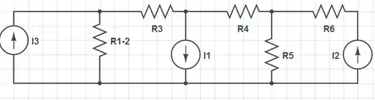
I was curious how this active pull down affected the circuit, so I implemented a similar circuit using CircuitLab. Since CircuitLab does not appear to have Schottky Transistors implemented, I used standard NPNs with Schottky Baker Clamps. I used values for the resistors found at this webpage.
simulate this circuit – Schematic created using CircuitLab
I ran a DC sweep on the input current, monitoring the voltage at the base of the output transistor.

As easily seen, the voltage at the base of the output transistor rises very rapidly to the forward voltage of a PN junction, even with uAs of current.
Then I ran the same test without the active pull-down circuit.
However, I was unable to discern any significant difference between the two results.

By the way, I tested to much higher levels of current, and the results of the two tests continued to match quite closely. I understand that the effect of \$V_{BE}\$ on \$I_C\$ is exponential, so even small variations in voltage might be significant, so perhaps the means I used to test the two circuits is not sensitive to show an effect by the pull-down, but at this point I wonder what is the purpose of the active pull-down.
For purely resistive base-to-emitter pull-downs, I understand that they prevent the base of the transistor from turning on until the supplied current is sufficiently high. However, in this case, the voltage at the base rises to a diode drop with very little supplied current.
My questions are:
Does the purpose of the active pull-down have something to do with performance / switching speed?
Does the purpose of the active pull-down have something to do with implementing low value resistors in integrated circuits?
Is there an easy way to implement a more sensitive test in CircuitLab that demonstrates a significant behavioral effect of the active pull-down circuit? (For example, is there a way to sweep two current sources at the same time, and in sync with each other?)
Is the way I am modeling Schottky Transistors too far from reality?
