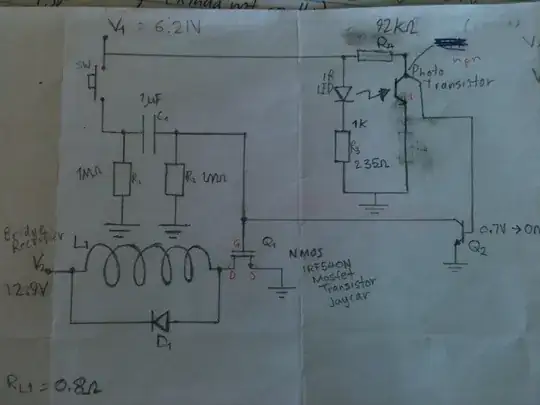
The schematic below uses an N-channel instead of a P-channel to block reverse-polarity voltage from occurring. This means the gate voltage (and Vgs) must be positive. But there are two options I've discovered so far to interpret how to calculate these values and I was wondering if you know which is correct (If any). If none of them is ok, then do let me know what is the right way to calculate this. In both cases we only look at if the polarity is right
System ratings: Vin=55V, Vz=35V, For use in a buck converter. NMOS is chosen over PMOS because they have a much lower Rds(on)
Since the mosfet is pulled to VIN, 55V travel to gate, and for a small period, it allows GND to pass through the mosfet and reach the Zener's terminal. From here on, there are 2 options:
OPTION 1 (the only way I see this working):
If in the P channel version, Vz is subtracted from Vin and enters the gate, then here it must be something like -(-Vz), so Vg = Vin -(-Vz) = 55+35 = 80V (Again, not so sure...). This would make the Vgs positive since Vgs=Vg-Vs=80-55=35V (so the zener adds its Vz to the voltage) and the circuit would be turned on
OPTION 2 (the zener operates just like in the P-channel version)
Vz gets subtracted from Vin and sent to the gate, which in this case would mean Vg=Vin-Vz=55-35=20V. But then Vgs=Vg-Vs=20-55=-35, which would be false since the mosfet wouldn't get turned on (Vgs(th)>0) (interesting thing, Vgs sets the gate voltage, but if it's positive or negative I'm not sure)
So what do you think? Which option is right? (if any)
Has anyone actually tried a circuit like this?

