4

I am currently trying to add a 7 segment display to my motorbikes gear indicator. requirements dictated by the bike:

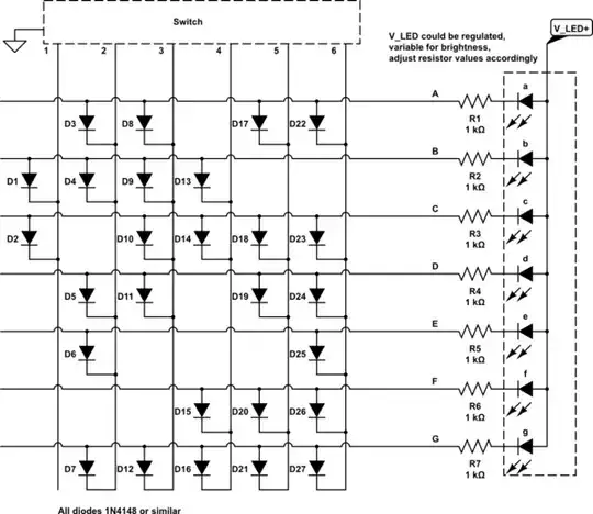
  1. there is a positional switch to ground for each gear. If you think it's like a rotary switch with the common connected to ground.
  2. 12v supply
  3. needs to be small / easily hidable.

I would like to avoid microcontrollers and additional voltage regulation needed if possible to keep costs and size down etc etc. so have been trying to achieve this with CD4000 IC's

This is what I have come up with so far. I just did a quick sketch to show what's on my breadboard so haven't put the display and the SP12T is just to be descriptive quickly with my existing Kicad footprints.

enter image description here

Now theoretically this should work, I think. Breaking it into parts it all functions properly, That is, I can get the output from the 4532 to display the binary correctly with LEDS directly from Q0-2. Obviously inputting the 4511 with a wire to power displays the numbers as expected. But, when I put them both together, all I get is either "0" or I have seen "8", but .

I am not sure if this is a reasonable approach. If I am missing an obvious mistake in my circuit.

Any help would be appreciated!

cheers

Circuit fantasist
  • 13,593
  • 1
  • 17
  • 48
  • 7
    Frame-Challenge: keeping cost, size & complexity down is an argument *for* a microcontroller, not against one. You could combine the functionality of everything in your schematic (pull-ups, inverters, priority-encoder, 7-seg decoder) into a single IC like a [PIC16F527](https://www.digikey.com/en/products/detail/microchip-technology/PIC16F527-I-P/3872386) for $1.50 or less. You can probably even get away with driving a common-anode display directly from the PIC if 10mA/segment is bright enough. – brhans Jul 30 '23 at 18:07
  • @brhans interesting idea using a PIC. I have no experience using them before, or any good knowledge about their capabilities. my experience is with projects that tend to be 'bigger' using stm32 and the like. Will do further research about the one you suggested though, thankyou. – Ashley Reid Jul 31 '23 at 20:21

1 Answers1

12

There’s a less complicated way to do this. Since you only have six positions you could use a diode matrix.

Each segment is connected to the switch through diodes so that in position 1 the cathodes for segments b and c get pulled low, in position 2 a, b, d, e and g get pulled low, etc.

You would need to use a common anode display and of course a resister for each segment, other than that you need a bunch of diodes like 1N4148 or SMT equivalent, 27 if I count right, and a voltage regulator to keep the brightness constant with changing battery/alternator voltage. The voltage could also be switchable or variable to change brightness for day/night.

schematic

simulate this circuit – Schematic created using CircuitLab

Edit: Maybe I should have Googled before drawing that whole thing out, I found someone else doing the same thing for the same purpose, so I guess it was a good idea. Looks almost exactly like mine except their gearbox switches positive so the polarities are reversed, and they have a position for neutral. They also show it done with a decoder and diodes to convert to binary code, uses less diodes but then you've got an IC. So there's a couple of options for you.

GodJihyo
  • 17,628
  • 1
  • 16
  • 45
  • 1
    I think this is a good thing to look into there is also the side benefit I am realising now that when no gear is selected (between switch positions) the display would be black and not show "0" as it would with my set-up. It may be possible to find a suitable diode array too. – Ashley Reid Jul 30 '23 at 14:37
  • 1
    @AshleyReid It's also pretty robust, no sensitive CMOS chips to worry about protecting. – GodJihyo Jul 30 '23 at 15:31
  • A nice illustration of how to make coders... – Circuit fantasist Jul 30 '23 at 15:57
  • 1
    With dual common cathode surface mount diodes you can use one package wherever there are two connected to the same switch output, such as D1 and D2. This should reduce it down to 15 packages, 12 with both diodes used, 3 with one diode used, which should save room on a PCB of you're going that route. – GodJihyo Jul 30 '23 at 17:37
  • 1
    For the numbers 0 to 6 the top and bottom segments of the LED display (segments A and D per your circuit diagram) always switch on together so you could save some diodes there. Actually the only numbers where they are different are 7 and (optionally) 9. – Level River St Aug 01 '23 at 01:46