1

I'd like to generate a square wave signal with Ton Toff time length based on two analog voltages between 0-5V, went with the method that seems the simplest, two 555 timer ICs with their trigger and output pins connected with capacitors (two separate ICs for prototyping, then probably a 556 for the real device). This should work like a two state state machine that switches between high and low outputs, basically what a 555 in astable mode would output.

Built a test circuit, and tried to test it with no control voltages applied to pins 5. My expectation would be a 50% duty square signal roughly T=20ms constantly switching between high and low states. But somehow one of the ICs is not getting triggered, and there's no oscillation. The IC that should be triggered has a roughly 1V constant voltage on pin 2, tried replacing the IC in question, but works the same with a different one.

555 monostable triggering other 555 timer

Am I missing something? Does this schematic make sense?

fflori4n
  • 31
  • 3
  • Show us a photo of the actual circuit you've built. Only 1V on pin-2 doesn't make sense with a 56k pullup. – brhans Jul 29 '23 at 23:19
  • 1
    You cannot use the full supply voltage range at pin 5 to modulate the pulse width. The useful threshold input voltage range is limited by 2 PN junction drops to GND, so acceptable operation starts above, say, 2 V at pin 5. You also change the trigger voltage level by changes in the control voltage. – Jens Jul 29 '23 at 23:35
  • 1
    (in short, by far the method that seems easier is a 1.50€ microcontroller. The whole bill of material would be reduced to 1 microcontroller, one decoupling capacitor, of which your 555-circuitry is missing two, by the way, and that's it. Microcontrollers are really really good at generating pwm style signals based on measurements of some voltages. It's like *the* thing that they were invented for) – Marcus Müller Jul 30 '23 at 00:56
  • @Marcus Müller "Does this answer your question? " No it doesn't, not at all. – Davide Andrea Jul 30 '23 at 12:36

1 Answers1

2

The problem was a wrong connection on the board, I accidentally connected the opto coupler output to the trigger pin, not the output pin - the schematic in the question works fine. After correcting my mistake, the oscillator works as expected.

enter image description here

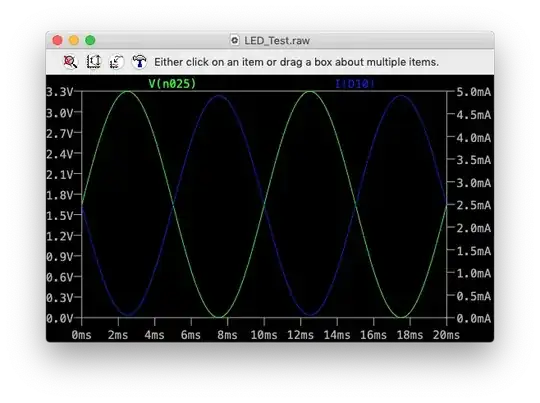
For reference: output looks like: enter image description here

signal on trigger pin looks like: enter image description here

The Ton and Toff times can be changed using the control pins (5), but the resoulution is not great, maybe allows 20% of change in Ton before the oscillator becomes unstable and stops when the control voltage is outside the valid range. The whole thing is very finicky. Maybe someone with more analog experience could make this work and use this for something.

As you said in the comments at this point a dedicated microcontroller is simpler, and can do much more. I'm going to abandon this idea and use an ATtiny85 or ATMega168.

fflori4n
  • 31
  • 3