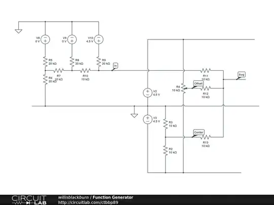
simulate this circuit – Schematic created using CircuitLab
I have really gotten stuck on this question where I need to calculate I1, I2, I3 and I4. The numbers for the circuit is: V(a)=2 V, V(b)=6 V, V(c)=8 V, R1=1 kiloOhm, R2=2 kiloOhm, R3=4 kiloOhm, R4=4 kiloOhm and R5=10 kiloOhm. I see four meshes and my go-to solution is the mesh current method with four equations where I create four mesh-currents consisting Ia, Ib, Ic, and Id. The equations I have created are:
- -6 + 2(Ia- Ib) + 1(Ia-Ic) = 0
- 4(Ib -Id) + 2(Ib - Ia) + 10(Ib) = 0
- -2 + 1(Ic-Ia) + 4(Ic - Id) = 0
- 8 + 4(Id -Ic) + 4(Id-Ib) = 0
These four equations are not adding up and I cannot understand why. My goal is to solve for Ia, Ib, Ic and Id.
FYI, the correct answer is I1 = -2 mA, I2 = 2 mA, I3 = 1 mA, I4 = -1 mA.
I would be so grateful if any of you could explain what I should do or think because I have been stuck on this for days.


