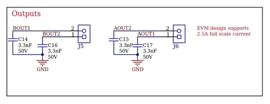
I am looking at the schematic of the DRV8434SEVM evaluation board for the DRV8483S stepper motor driver and I see they've put these 3.3nF capacitors on the outputs going to the stepper motor coils. I cannot find any mention about doing this in the datasheet of the driver or anywhere else, why might you want to do something like this?

Asked
Active
Viewed 62 times
2
ultraturbonoob
- 55
- 4
1 Answers
1
The printed (PDF) schematic shows these are DNP (do not place), so it seems a non-issue.
Perhaps they are available as an option to slow edge rate from the inverters.
I wouldn't recommend it myself; it's a crude method that increases switching loss.
Better is a series inductive element (which limits current drawn from the inverter, thus having less impact on efficiency), placed before the capacitor, with damping provided either by using a lossy inductive element like a ferrite bead, or an R+C in parallel with the C.
Tim Williams
- 22,874
- 1
- 20
- 71
-
@greybeard thanks! – Tim Williams Jul 29 '23 at 05:25