Basic idea
The difficulty of implementing this circuit solution comes from the fact that things are reversed - the LED should light up when there is no voltage and no current flows. This problem can be solved with a clever trick - the LED lights up in the high impedance state and turns off in the other two states by connecting another diode with a lower forward voltage in parallel.
Version 1
The LED HI indicating the high impedance state is "stretched" through the "pulling up" (R2) and "pulling down" (R3) resistors between the supply rails. The transistors Q1 and Q2 act as transistor switches that can connect one of the diodes (D1 or D2) in parallel to the LED to switch it off.
High-impedance indicator
Low input voltage: Q2 turns on and connects D2 (0.7 V) in parallel to HI LED (1.8 V). So all the current is diverted (steered) from HI to D2.
simulate this circuit – Schematic created using CircuitLab
High impedance: Both Q1 and Q2 are off so all the current flows through the HI LED.
simulate this circuit
High input voltage: Now Q1 turns on and connects D1 (0.7 V) in parallel to HI LED (1.8 V). So all the current is diverted (steered) from HI to D1.
simulate this circuit
Analog comparator
The circuit works analogously to the above, except that instead of a high impedance state, an input voltage Vin = Vcc/2 is applied.
simulate this circuit
So, in the middle region, the voltage across the LED changes from 0.7 V to 1.8 V ...
... and the current is maximum.
3-state digital indicator
If we replace the Si diodes with LEDs, all the three states will be indicated. HI LED must have higher forward voltage than LOW and HIGH LEDs. It can be the same as them if we connect an Si diode in series (0.7 V is added).
Low input voltage: Q2 turns on and connects LOW (1.8 V) in parallel to the string HI-D (1.8 V+ 0.7 V = 2.5 V). So all the current is diverted (steered) from the string to LOW.
simulate this circuit
High impedance: Both Q1 and Q2 are off so all the current flows through the HI LED.
simulate this circuit
High input voltage: Now Q1 turns on and connects HIGH (1.8 V) in parallel to the string HI-D (2.5 V). The current is diverted (steered) from the string to HIGH.
simulate this circuit
Analog indicator
simulate this circuit
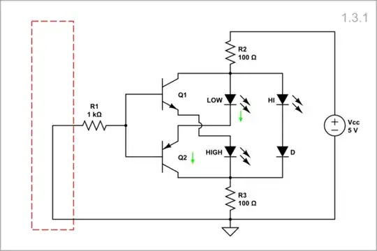
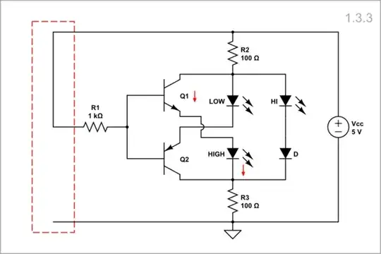
Version 2
A more beautiful circuit solution can be obtained if we connect the transistors and diodes as shown below. Here the transistors not only turn on a diode in parallel with the LED but also short out the other diode.
3-state digital indicator
Low input voltage: Q2 turns on, shunts HIGH LED and connects LOW (1.8 V) in parallel to the string HI-D (1.8 V+ 0.7 V = 2.5 V). So all the current is diverted (steered) from the string to LOW.
simulate this circuit
High impedance: Both Q1 and Q2 are off. The HIGH and LOW LEDs meet the requirement that the sum of their voltages is higher than the total voltage of the HI-D diode string. As a result, all the current flows through the HI LED.
simulate this circuit
High input voltage: Now Q1 turns on, shunts LOW LED and connects HIGH (1.8 V) in parallel to the string HI-D (2.5 V). The current is diverted (steered) from the string to HIGH.
simulate this circuit
Analog indicator
The circuit works analogously to the above, except that instead of a high impedance state, an input voltage Vin = Vcc/2 is applied. Both Q1 and Q2 are off and all the current flows through the MID LED.
simulate this circuit
Version 3
simulate this circuit
See more in my Codidact paper 3-LED voltage indicator (an inventor's story).


