2

I am attempting to build/create/design/whatever a way to control my RGB LED strips via a USB or ethernet interface. These strips consume a lot of power and the mass produced controllers suck. I would also like independently controllable "zones" if you will, so ideally this device could power 1 or more strips.

Since a picture is worth 1,000 words I've attached an image of what I am trying to accomplish. Does anyone know of something like this commercially available, or how I can practically create something that will power this many LEDs? At a minimum I would really like each device to power 3 strips at a time which is quite a bit of power. I'm am very new to EE, so this is all kind of overwhelming to me.

enter image description here

David
  • 131
  • 1
  • 4
  • I'm trying to do something similar as well, except I want to incorporate wireless control. Basically I want to wirelessly control 5 RGB LEDs independently. Serial data would be sent through a computer program via USB which would be connected with a wireless transmitter. The transmitter would communicate with 5 wireless receivers each receiving an independent signal at an independent time and would control the corresponding LED. Any input on specific hardware that would be needed to do this and how to design this type of network would be greatly appreciated. –  Jul 28 '13 at 18:07

2 Answers2

5

Since you are new to electronics, I would suggest you get a development system that will give you an Ethernet connection as well as having USB output control. While I would normally never suggest the use of something like Arduino with appropriate shields or Raspberry Pi, in this case, it makes the most sense for you to get a system with a ton of online support as well as plenty of source code that should work for what you are trying to do, and both of these have that.

However, for typical circuits, even those involving some pretty complex circuitry, I would recommend you skip the development boards all together and learn to design your own circuit around a microcontroller chip, adding whatever external hardware you need. The only real reason I am suggesting a dev board in this case is because you are new, and I am imagining it will take you a long time to get both an Ethernet and USB interface up and running.

LED Control

As for the external hardware to control the LEDs, that is pretty easy to explain, but there are quite a few different ways to do it. To start, the RGB LED is made up of three internal LEDs: red, green, and blue. The resulting color is determined by the intensity each individual LED. In order to control the color, you will need a way to dim each of the three internal LEDs. The exact wiring of a circuit will be determined by what type of LED is use:

  • Common Anode: Each LED shares an anode (side for positive voltage) but has its own cathode.
  • Common Cathode: Each LED shares a cathode (side for negative voltage) but has its own anode.

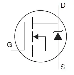
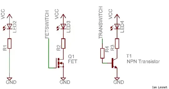
A very common way to control the LED brightness is by using Pulse Width Modulation. To drive a large current, a transistor is commonly used as such:

MOSFET LED Switch

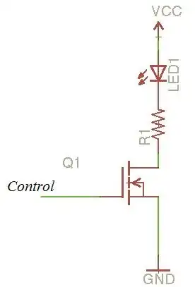
In this circuit, the MOSFET (Q1) is being used to switch the LED to ground. This would be ideal for the common anode RGB LED as each internal LED should have its own cathode. The brightness is controlled by pulsing the base of the MOSFET. This pulse should be high enough to avoid any noticeable strobe. A safe number is 200Hz. The duty cycle of this pulse (the ON time vs the OFF time) then controls the brightness of the LED. The resistor R1 is necessary to limit the current through the LED.

Here is a discussion on efficient ways of driving LEDs such as a current driver.

If you want all of the LEDs to be the same color, then you would need three of these transistor switches and three PWM outputs with every red, green, or blue cathode (plus current limiting resistor) in parallel.

You could divide the control up as much as you like to set different LEDs to different colors at the same time. The PWM output can be created manually in software, or done automatically using the microcontroller's dedicated internal hardware functionality, although the number of dedicated internal PWM channels is limited in a device. Software versions are limited by the total number of I/O pins unless you resort to using I/O expanders or shift registers to increase the number of outputs available. There are also numerous multiplexing schemes, but they can become overly complicated.

Choosing a Suitable MOSFET

There are a couple of important things to note about picking the right part:

  • Drain to source current (I_ds) - this is the maximum current that can be switched. Give yourself plenty of overhead room!
  • R_ds(on) - this is the MOSFET resistance while it is saturated (switched on). The lower this value is, the more efficient the switch will be (less power dissipation in the switch)
  • Gate Threshold voltage - this is the minimum voltage necessary at the gate for the MOSFET to start conducting. It needs to be a bit higher than this to be fully saturated. For control from a microcontroller, you will want a "logic level gate" which has a very low gate threshold voltage. The R_ds value will drop as the gate to source voltage increases.
  • Power dissipation - The MOSFET will need to be able to dissipate at least the expected current (I_ds) squared times the expected drain to source resistance (R_ds).

It is also a good practice to put a pull down resistor (10k or so) at the MOSFET gate to make sure it is OFF when you want it to be (such as during a system reset).

Additional Information

Unfortunately, I don't know much of anything about the R Pi, so I can't help you there, but I do know you would be programming the GPIO pins as outputs to drive the MOSFET gates. Keep in mind that the Pi has 3.3V I/O pins, so you will need to get a MOSFET with a gate threshold of a bit less than that, try 1V - 2V. The circuit can be built on a breadboard to test it but should be soldered to a perf board or PCB when you are happy with it.

Here is a good MOSFET that should work well. See if you can find the characteristics I mentioned above in this datasheet.

Kurt E. Clothier
  • 4,419
  • 18
  • 31
  • Holy cow I wish I could upvote you more than once. Okay I already actually own a Raspberry Pi (I'm a big computer guy) - and I'm sort of following what you're saying, my next question is: how/where do I build one of these circuits with the Pi? – David Apr 29 '13 at 13:03
  • @David, see the additional information I added at the bottom of my answer. Hopefully that helps a little. – Kurt E. Clothier Apr 29 '13 at 20:17
  • 1
    I'm working on something similar to this, but I'm using DMX 512 instead of ethernet or usb. I'm using a similar configuration as mentioned by Mr. Clothier, with the exception of using TIP122 darlington pairs instead of mofets and TLC5940s to drive the TIP122s. This gives me more room to add strips. @David If you are interested I can share the schematic with you. – Hair_of_the_Dog Apr 29 '13 at 22:29
  • My good sir, I don't have a freaking clue what you just said, but I would be most appreciative of that. Adding more strips sounds exactly like what I want to do. :) – David Apr 30 '13 at 00:13
  • @Hair_of_the_Dog, Yes it could work similar using BJTs instead of FETs. But given the low switching frequency needed for LEDs, and the decently sized current used by the strip, it would be more efficient and much cheaper to use a MOSFET than a Darlighton pair and that driver. Plus, the MOSFET I mentioned can switch 50 Amps at a high temperature of 100 deg C with 3.3V at the gate - which should leave plenty of head room for adding more strips. – Kurt E. Clothier Apr 30 '13 at 01:02
  • @KurtE.Clothier I found that the TIP122 were a bit cheaper than the MOSFETS I was looking at. For what I am doing I don't need to switch more than 5 Amps per transistor (really more like 1.5A per channel). BTW: I'm not advocating using a power darlington pair over a MOSFET here (I think both, for the most part, will work fine). It just worked for my project. – Hair_of_the_Dog Apr 30 '13 at 05:40
  • @David Here are the links to the LED strip driver project I'm working on. http://jeremyveleber.com/YfgGn http://jeremyveleber.com/BSp4N http://jeremyveleber.com/uXvrD BTW: I'm using an ATX power supply to power the whole thing. – Hair_of_the_Dog Apr 30 '13 at 05:41
  • @Hair_of_the_Dog, Agreed. What I meant was that the FET(s) would be cheaper than the TIP122 and TLC5940 combination, at least unless you were using a lot of transistors to switch different groups of LEDs, then the extra cost of the FET would overtake the cost of the TLC5940. So either will work fine, just depends on what you are most comfortable using. – Kurt E. Clothier Apr 30 '13 at 07:45
  • @Hair_of_the_Dog, thank you so much! I am currently using a plain ATX power supply to run my current LEDs as well! – David Apr 30 '13 at 14:01
2

For USB I'd use one of the AVRs with hardware USB (like the ones on teensy, leonardo, etc). Have the PWM outputs driving logic level MOSFETs. (assuming you want to control brightness... but that will do on/off too).

The mosfet will sink the current (be connected to the ground side of your strips, with +12 to the other side of the strip).

Like the middle portion of this drawing, except the resistor and LED are integral to the strip, so the strip would be wired in here.

mosfet diagram

You'll need a mosfet that will be on with 4-5V, capable of a couple amps, and 20V or so. more current/voltage handling never hurts, though. Low Rds will help efficiency. (per channel).

Marko
  • 825
  • 4
  • 8
  • Thank you for the reply, I'll spend the next few days trying to figure out what the heck any of that means :D – David Apr 29 '13 at 00:02