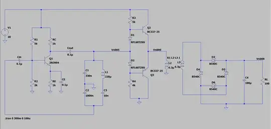
I used LTspice to simulate a oscillator circuit to convert DC to AC. The oscillator is then connected to a class AB power amplifier to increase the circuit current. The load of the Class AB amplifier is two coupled inductors to simulate wireless charging pad. The other side of the coupled inductor is connected to a rectifier circuit to convert AC back to DC.
This is the LTspice circuit:
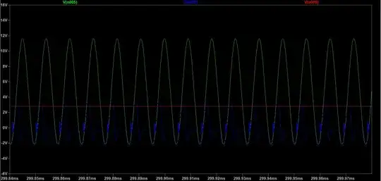
This is the simulated waveform:
V(n005) is the voltage output of oscillator circuit and input of class AB amplifier
V(n006) is the voltage output of class AB amplifier.
V(n009) is the voltage output of rectifier circuit.
Based on the simulation results, I have some questions:
Is the output of the class AB amplifier supposed to look like this?
Why is the output of the rectifier circuit so low?
For the output of the oscillator circuit, what should I do to make a DC offset so the the AC voltage can be completely positive?
Would doing this increase the output of the rectifier circuit?
Overall, how do I improve on this circuit?

