I was preparing this lab sheet and the circuit we are analyzing is
The theoretical time constant of this circuit is given by
$$\tau=R_{th}C_1=\left(R_1 // R_2 + R_3\right)C_1 \simeq 207.3 \,\, \mu s $$
Nice and straightforward.
Now to analyze the circuit I have considered the ideal source, resistors and also forced the capacitor to be ideal.
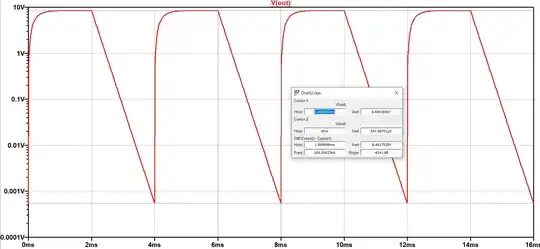
I have obtained this logarithmic plot of the output voltage
The thought process was considering the discharge of the capacitor
$$V_{out}= V_{charge} \times e^{-\frac{t}{\tau}}$$
with
$$V_{charge} = \frac{R_2}{R_1+R_2} \times V_{ON} \simeq 8.485 \,\, V $$
Taking the logarithm means that the time constant is given by the inverse of the slope
$$ \ln \left(V_{out} \right) = \ln \left(V_{charge} \right) - \frac{t}{\tau} $$
From the graph and the plot points follows that
$$\tau \approx 235.7 \,\, \mu s$$
So there is a difference of \$ 28.4 \,\, \mu s \$ between the theoretical and simulated value.
I am trying to find the reason behind this.
At first I was like "well there are some imprecisions on using the cursor values, due to the discretization so perhaps there is a change on the slope by considering this two points.
But then I did the "pseudo-theoretical" calculation of the time constant by considering that the capacitor discharges from \$ V_{charge} \$ to \$ 0 \$ during half the period \$ \left(2 \,\, m s \right) \$, which gives \$ \tau = \frac{2 \,\, m s}{V_{charge} - 0} \simeq 235.7 \,\, \mu s \$ so it is not due to imprecisions with the cursors the "pseudo-theoretical" calculation gives a similar value.
There might be something I am overseeing in this? Perhaps the slope method is also an approximation somehow to the time constant? What is exactly going on here?

