Refering to my previous question, I want to drive a bunch of High power LED drivers (Datashsheet AL8860WT-7) With a Pixel-IC (Datashsheet P9813).
My project so far: connecting the R, G or B Pin of the Pixel-IC directly to the driver does not work, as these pins seem to need some kind of a Pullup or other things which I simply don't know. This is the from the P9813 Datasheet:
 The resistor RB seem to work like a Pullup in this case, but I can't figure out, how this would work with the AL8860 Driver. This Driver needs a PWM signal > 2.5V to switch the load with full current.
When I connect the P9813 with the pullup-resistor (RB=2.2k) shown above, I get a constant voltage of about 1V at the drivers' input with a ripple of about 0.1V.
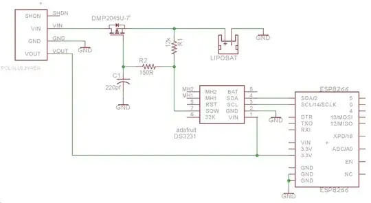
This is the circuit so far:

I would be very happy to figure out:
- Do I have to use a transistor to switch the driver?
- if no: What do I have to change?
- if yes: would I rather use a bipolar transistor or a mosfet? these cheap levelshifting modules for example often use BSS138 mosfets for I2C stuff etc... Unfortunately I have these only in a SOT-23 package laying arround and its a pain to get these tiny chips working on a breadboard.
Your advice will be highly appreciated!
edit: I have successfully used a Bipolar transistor to get the driver to work with the P9813, but with a inverted signal. So I thought I'll use two transistors to invert the signal twice.

