11

I disassembled a cheap tweeter because I wanted to use only the inner part of it since it is just about 5mm tall (1/4 inch). I thought the coil that surrounds it was just a cheap inductor to "short out" low frequency and protect the tweeter.

Turns out that when I connected only the piezo with the capacitor in series, it sounded lower in frequency and loudness. I could verify this using a phone app called "Spectroid" and comparing it to the other unit that came in the same package and was still undamaged. It appeared to make no difference if I included the capacitor in series with the piezo or not.

How can this coil do that? On close inspection I noticed it connects on three points which means it is actually two coils with one common connection.

These units are made as cheaply as possible, (it costs about US$1.50 a pair), so I think the coils are there for some real purpose, and it appears that it somehow make the tweeter more sensitive/louder.

¿How does it make the unit louder and how does it make it shift the frequency response up?

This picture shows the empty casing, the undamaged inner assembly to the right and, on the left, the plastic dome with piezoelectric driver adhered inside it, with a small pcb and capacitor under it: (AAA cell for scale)

enter image description here

This picture shows a closeup of the pcb. The arrows mark the point where the coils are connected. The one near 7 o'clock position has two wires going to the coils. The piezo is connected to the pads positioned at 12 and 6.

enter image description here

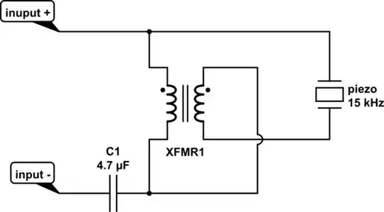
This is my attempt at a schematic for the whole unit as far as I can see:

enter image description here

RussellH
  • 12,496
  • 2
  • 9
  • 34
Jahaziel
  • 285
  • 4
  • 12
  • 2
    It looks like an auto transformer, which would make sense since piezos are a bit quiet in my experience. Got access to an oscilloscope? – Bryan Jul 15 '23 at 23:48
  • @Bryan, no, I don't have an oscilloscope nor access to one. Just a basic multi meter. – Jahaziel Jul 15 '23 at 23:58
  • 3
    @Jahaziel I'm curious about the details, so +1. Nice question to ask. And I really like the brain of anyone who, upon encountering something like this, stops for a moment and wonders about why a thing is the way it is. I have some guesses (impedance matching between the typical amplifier output and the piezo.) But I really don't know. And I'd like to hear from someone who actually does know enough to be able to design what you see there. We both may get lucky. – periblepsis Jul 16 '23 at 00:09
  • Hmm. What’s the coil wound around? It would have to be metallic at these frequencies - I doubt a ferrite or air core would get it done. – Bryan Jul 16 '23 at 00:13
  • I have heard more expensive piezo horn tweeters that sound awful with resonant peaks and cancellation nulls in the frequency response. These extremely cheap piezo tweeters must sound worse. The dynamic hifi tweeters I use sound perfect and wonderful. – Audioguru Jul 16 '23 at 00:38
  • @Bryan, a simple plastic form. – Jahaziel Jul 16 '23 at 00:40
  • 1
    @Jahaziel for audio tinkering a pocket oscilloscope is quite useful - assuming you're going to make a habit of it. Yes, they're annoying junk compared to the benchtop ones in the lab, but they're also about 30× cheaper. – Chris H Jul 17 '23 at 08:39

2 Answers2

6

I'm going to draw the diagram differently, but the electronics is the same, Bryan's auto transformer is correct. The diagram is not different from glen_geek's diagram or the OP, just rearranged t reveal the auto transformer relationship of the coils.

Clearly the voltage from the amplifier is applied to the upper coil and then through transformer action the voltage across the entire transformer is applied to the piezo element.

Piezo speakers are very high impedance and require a high voltage to flex them into making sound. Whether this is 1:2 or higher would need to be measured. An speaker design engineer would probably know.

How does it make the unit louder and how does it make it shift the frequency response up?

So the voltage is stepped up and also the impedance is stepped down to match the amplifier drive level. This is how the coils make the sound louder.

The series capacitor blocks low frequency and dc. The transformer could also be wound to block low freqencies as well so that the speaker can have its name "tweeter".

schematic

simulate this circuit – Schematic created using CircuitLab

Sorry CircuitLab would not let me draw the bars that indicate the transformer core.

RussellH
  • 12,496
  • 2
  • 9
  • 34
  • at least in this case the transformer would be air core. These cheap units have no metal in them other than the thin wires (...). Also, thanks for rearranging the drawing. I makes it way more clear to me that the speaker receives a higher voltage across its terminals. – Jahaziel Jul 16 '23 at 01:14
3

Almost. I'd guess the transformer is a 1:2 stepup. This diagram has phases switched from OP's:

schematic

simulate this circuit – Schematic created using CircuitLab

glen_geek
  • 23,591
  • 1
  • 22
  • 50