0

Given 1 hall sensor. It can be in:

  • State 1: Static 0 (no oscillations)
  • State 2: Static 1 (no oscillations)
  • State 3: Edging 0/1 at different frequencies

Given also an MCU which counts the positive edges. When there are no edges for a long time, the MCU goes deep sleep for power saving reason. There is no ability for the MCU to awake from the deep sleep by external interrupt. (Frankly there is light sleep mode but it does not work properly => it's excluded out of the picture hence.)

The challenge is:

  • Detect start of the oscillations (state 3) after significant pause (states 1 and 2). Once the oscillations detected, pull the RST pin of the MCU down for 10 ms.

The "pause" can be just 100 ms or any more.

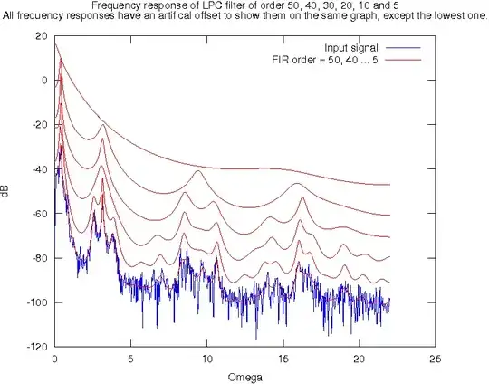
Thanks to @periblepsis, the graph which describe the challenge is: enter image description here

For this challenge I use another MCU, of microamperes, which detect the state 3 and resets the main MCU. This adds some complexity to the circuit, more firmware to maintain, relatively low whole solution reliability.

This, This, This and This are similar parts of possible solution: they all detect any edge and generate RST pulse. This will reset the MCU on every single edge. However, the challenge states a detection of an edge after steady 0 or 1.

My question is:

  • How to implement fully electronic detector of oscillations (state 3) after the after significant pause (states 1 and 2)?

I guess it should be some gates and/or FETs... A reference to similar schematics or names of relevant building block will be appreciated.

UPDATE: I tried to run Falstad sim on the 2nd idea of @Michal enter image description here It detects the positive edge pretty well. And it is easy to disable that circuit from MCU once awaken.

The problem here is that if the Hall sensor starts rotation at high RPM then MCU might not have enough time even to reach 1st line in the code and set GPIO to 1 for circuit off. This means the MCU will be resetting at the frequency of Hall sensor while it is rotating.

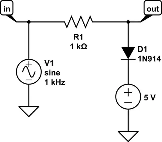
The circuit proposed by @periblepsis simulated and works just like repeater for the input. This is mayby my fault: I don't know which values to set for resistors and capacitors. I set "rule-of-thumb" values...

In similar "repeater" way simulated the 1st idea of @Michal

Ivy Growing
  • 335
  • 4
  • 12
  • Why not use a jk latch with master reset. Hold master reset whilst the mcu is on, with flip on edge. – user1937198 Jul 14 '23 at 18:19
  • http://www.ganssle.com/debouncing.htm – Scott Seidman Jul 14 '23 at 19:43
  • Ivy, sounds [like this](https://i.stack.imgur.com/rVjLs.png) is what you are asking for. Can you confirm? (I can't tell from your writing.) If so, then there are two, not one, timers involved. One can be handled by a capacitor and a current source. But the other will need to be a one-shot of some kind. Also, edges in both directions suggest the use of a discrete schmitt trigger (which can have two outputs built-in that can be each passed through a series capacitor and diode to a pull-down and then to a BJT that can reset the capacitor.) But you are asking a lot for a simple answer here. – periblepsis Jul 15 '23 at 07:35
  • Ivy, more specifically, [this is where](http://i.stack.imgur.com/EZCDU.png) I'm thinking you are headed. – periblepsis Jul 15 '23 at 07:49
  • @user1937198 Thank you. I'm going to learn what "jk latch with master reset" means. – Ivy Growing Jul 15 '23 at 08:58
  • @ScottSeidman yes, debouncing it's nice idea for what's needed. After debouncing circuit the one-shot monostable can be added to generate reset pulse. I'm going to learn how to implement debouncing circuit in hardware without impacting the MCU original input. – Ivy Growing Jul 15 '23 at 08:58
  • @periblepsis That's exact chart what's needed. One picture illustrates the question better than all the words. May I copy it into the question body, please? Thank you for the circuit reference. I'll try to implement it. – Ivy Growing Jul 15 '23 at 08:58
  • @IvyGrowing Of course. Feel free. – periblepsis Jul 15 '23 at 09:10
  • @IvyGrowing Are you open to 555's, as well? Or similar devices? Or is a discrete circuit preferred? Discretes aren't boutique, are cheap as dirt, and will always have parts available forever. But the 555 is also likely to be around forever, as well. So I can't signal a preference on that account. It's just that with discretes that 100 ms timing requires a FET to achieve (BJTs drain unpredictable currents.) A 555 can easily handle it. – periblepsis Jul 15 '23 at 22:41
  • @IvyGrowing If discrete, then [this](https://i.stack.imgur.com/YT7pM.png) would be the direction I might consider. It's how might do something like this *back in the day*. Would work in 1965 and would still work today more than 50 years later. Of course, a dedicated MCU would be still cheaper, more configurable as new requirements enter over time, take up less space, etc. But an MCU requires the maintenance of a tool chain over time, coding and validation, and is boutique and supplies may vanish, also. – periblepsis Jul 16 '23 at 04:59
  • Let us [continue this discussion in chat](https://chat.stackexchange.com/rooms/147245/discussion-between-ivy-growing-and-periblepsis). – Ivy Growing Jul 16 '23 at 06:09
  • @IvyGrowing Your edit provides some useful info and I may be a bit at cross-purposes with your goals. Are you wanting to wait until the rotation stops or slows down enough that you have time to wake up and execute some instructions? Or something else? (I'm just looking at the newer editing info in your question.) – periblepsis Jul 16 '23 at 06:47
  • @periblepsis The chart you crafed explains 100% what's needed. After the MCU sleeps, wait for pulses. If 1-2 pulses given in 50-100 ms, then ignore. If more than 2 pulses happened in 50-100ms then pull a line down for 10ms only once for seconds. – Ivy Growing Jul 16 '23 at 06:59
  • @IvyGrowing Okay. I can grok that. But I'm still worried that you may prefer ICs over discrete. Any preference? – periblepsis Jul 18 '23 at 10:48
  • @periblepsis Any IC is ok - no specific preference. Except another MCU and another FW. I tried MCU already. Pure electronic solution mught work better. – Ivy Growing Jul 22 '23 at 12:28

4 Answers4

2

This can be done with BJTs. But since you are open to 555 timers and since these come in paired packages, too, let's use 555's for most everything. Easier to explain, too, should there be further questions.

Concepts

The basic idea is to use a 555 monostable for the \$100\:\text{ms}\$ hold period and another 555 monostable for the \$10\:\text{ms}\$ wake-up period. A third 555 re-triggerable monostable will be used to check to see if the oscillations continue long enough. So that's three devices.

Along with that will be a few BJTs and some scattered resistors and capacitors. \$Q_3\$, for example, is used to trigger the \$10\:\text{ms}\$ wake-up period if and only if the \$36\:\text{ms}\$ retriggerable monostable is still high when the \$100\:\text{ms}\$ monostable falls low. (I currently imagine so, anyway.)

Implementation

I decided to test only with the CMOS version of the 555 timer. If you prefer to use the bipolar version, it may still work.

Here's the schematic:

schematic

simulate this circuit – Schematic created using CircuitLab

Here are the output examples, on left and on right:

enter image description here

Here's what happens if the oscillator continues a little longer, still:

enter image description here

Note that at some point the \$100\:\text{ms}\$ monostable does re-fire. But there's no 2nd wake-up here.

However, there could be one if the oscillation continues long enough to push the \$36\:\text{ms}\$ re-triggerable monostable out past the falling edge of the \$100\:\text{ms}\$ monostable.

I think you should be perfectly fine with that behavior, though.

Feel free to ask questions.

Here's my LTspice schematic that produced the above waveforms:

enter image description here

Here's a Falstad version.

periblepsis
  • 3,766
  • 1
  • 1
  • 10
  • Thank you @periblepsis. That's great functionality. Itried to simulate it in falstad https://tinyurl.com/2dy87olx, because I cannot manage to simulate it in circuitlab. In falstad the last monostable does not fire. I tried to debug it and I think the problem is in analog circuit Q2-Q3. Voltage on base Q2 never goes higher than 320mV and it does not trigger the U2. – Ivy Growing Jul 23 '23 at 08:47
  • @IvyGrowing I've added the schematic from LTspice. I'm using Vcc=5 V. I generally don't trust Falstad. But that's just me. Were you using CMOS variety of 555? Just curious. Or not? Either way it should still work. You could just eliminate the capacitor between the two 47k resistors. Won't hurt anything (except at power-on where that cap might help avoid a false trigger of the final 555.) The falling edge of the 100ms 555 (on the order of tens of nanoseconds) should be fast enough to trigger the BJTs leading to the final 555. – periblepsis Jul 23 '23 at 09:39
  • @IvyGrowing I've added a [falstad version](https://tinyurl.com/2a923zfh) that appears to work okay. First time I've ever tried to use it with anything serious. It doesn't seem to have the ability to specify a number of pulses and then stop. But perhaps you know more about it and can fix it. – periblepsis Jul 23 '23 at 10:42
  • @IvyGrowing Kind of a flaky simulation, though. It seems to work but if I play around much with the display controls then it simply stops working well. LTspice just works. – periblepsis Jul 23 '23 at 10:50
1

Idea below:
On the input is Voltage doubler reacting to AC or pulsed signal only.
(use schottky if you work with low voltage like 3v3)
Once C1 voltage reaches Vcc/2 schmitt trigger generates logic 1 on its output.
Schmitt trigger fires a monostable which is set to 10ms (or whatever).

schematic

simulate this circuit – Schematic created using CircuitLab

Another solution (below) is to use a R1C1 derivator on input with time constant of 10ms what generates a reset pulses after every Low-To-High transition of Hall sensor. But, after first MCU reset immediately set Pin_0 High to block further resetting. Of course do not forget to set Pin_0 Low when MCU is going to sleep.

schematic

simulate this circuit

Edit (July 16):

To get nice clean reset pulse you have to use a latching transistor M3. PNP also NPN version is possible. In simulation I put an AC detector in front of trigger transistor M2.

schematic

simulate this circuit

Blue is M2_gate voltage, orange is Reset pulse. enter image description here

  • Thank you. Both ideas seems reasonable and fulfilling the requirements of the question. I am assmbling them now. Will accept the answer once it works. – Ivy Growing Jul 15 '23 at 09:15
  • thank you for the extended ideas. I simulated all variants and updated the resutls in the question. The last variant iś not just a repeater. M1 and M3 work as multivibrator. M2 waits for the threshold reached to trigger the multivibrator. However, Hall sensor gives strong 0-VCC-0 pulses. So the voltage multiplier is not needed here. I am failing to match RC for 2-3 edges in 50-100 ms. You gave me an idea to use monostable. I implemented it on 555 + signal inverter. Disabling it with MCU as you recommended. Testing it... Will update on results. – Ivy Growing Jul 16 '23 at 06:39
  • RC high pass to RC low pass is perfect for filtering 3 short pulses after long steady. High pass puts over the AC component only while low pass is a storage of it. – Michal Podmanický Jul 16 '23 at 07:51
  • Interesting. I have learnt that RC circuits work well for AC. For the DC pulses they behave differently, like integrator or differentiator. – Ivy Growing Jul 16 '23 at 10:58
0

My own answer is derived from @periblepsis'. It is a bit simpler but satisfies the challenge.

This answer is inspired by words "monostable" and "disable reset" from the answer of @Michal. 2 CMOS 555 timers are used.

This is the minimalist solution for the challenge:

How to implement fully electronic detector of oscillations after the significant pause.

enter image description here

Simulate.

The principle is:

  • While MCU is in deep sleep, the RST pin of the MCU is pulled up. This allows the MCU to count time of the deep sleep.
  • When square wave starts, the monostable generates pulse in the original width of the pulse, no matter how fast or slow the oscillations are. This casues the MCU restart => I.e. deep sleep ends.
  • No more pulses produced for long enough time, 500ms in my case, to allow the MCU boot.
  • Once the MCU boots, the first command pulls the RST of 555 down -> from this moment the 555 is unable to generate more "reset" pulses. So MCU can doo all its work and go sleep safely.
  • When the MCU sleeps the RST of 555 is pulled up again and it is sensitive to new oscillations.

It was tested on the real electronics and MCU formware and works as expected.

enter image description here

Ivy Growing
  • 335
  • 4
  • 12
0

schematic

simulate this circuit – Schematic created using CircuitLab

This circuit element goes high when the input changes state. You'd have to arrange the wakeup IRQ to be only enabled during low power mode to avoid having to handle continuous interrupts during normal operation. R and C values are application dependent.

elchambro
  • 796
  • 4
  • 13