3

We have designed a inrush controller using the LTM9100 controller. The LTM9100 basically controls the ramp rate of the gate voltage, which in-turn controls the raise time of the DC bus across the load. Our nominal DC bus voltage is 300 V, but the problem we are facing is that, the moment we enable the inrush operation of the LTM9100 (enable pin), the MOSFET fails, we have tried this with multiple MOSFETs (MSC025SMA120B4, NTH4LN019N65S3H to name a few) and its always the same result. But when we lower the nominal voltage to about 150 V everything works perfectly.

Could you kindly suggest what may be the possible root cause of this and any possible solutions?

We tried decreasing the ramp rate (CR in circuit), but the MOSFET still fails. After some googling, we thought it may be because of spikes at the drain, but the MOSFETs we used are rated for 1200 V, I'd be surprised if 300 V could generate that much spike? Attached is the exact circuit that we have used. enter image description here
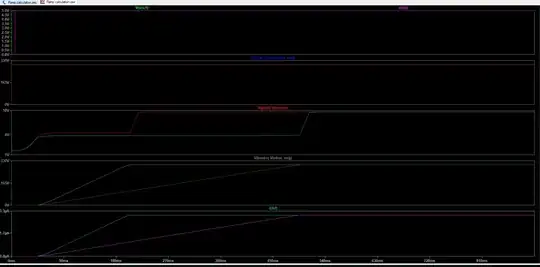
And these are the expected results: enter image description here

Aaron
  • 7,274
  • 16
  • 30
AK47
  • 75
  • 7
  • What’s the peak inrush current? What’s the SOAR of the MOSFETs used at 300 V? What’s the ramp rate? – winny Jul 11 '23 at 12:44
  • Simulation is a useful tool. But when testing, an oscilloscope is the way to go. Try to capture a device failing - I bet the Safe Operating Area is being violated or there is ringing or oscillation somehow. Remember, *oscilloscope grounds are connected together* and to the *Earth ground*. Is this on a heatsink? – rdtsc Jul 11 '23 at 13:09
  • 1
    Does this answer your question? [Soft start circuit problem](https://electronics.stackexchange.com/questions/577079/soft-start-circuit-problem) or maybe [Heat Dissipation Calculation for MOSFET](https://electronics.stackexchange.com/questions/472375/heat-dissipation-calculation-for-mosfet/472587#472587) or maybe [Burning a Power MOSFET](https://electronics.stackexchange.com/questions/397467/burning-a-power-mosfet/397511#397511) or [Mosfet thermal problems in linear applications](https://electronics.stackexchange.com/questions/555256/mosfet-thermal-problems-in-linear-applications/555302#555302) – Andy aka Jul 11 '23 at 13:48
  • or [MOSFET keeps blowing out](https://electronics.stackexchange.com/questions/636590/mosfet-keeps-blowing-out/636611#636611) or [MOSFETs in parallel, combining heat-sharing and ballast resistors?](https://electronics.stackexchange.com/questions/582440/mosfets-in-parallel-combining-heat-sharing-and-ballast-resistors/582487#582487) – Andy aka Jul 11 '23 at 13:53
  • @winny The peak inrush current can be set by CR capacitor, with the CR of 30nF , the current is limited to 0.36Amps and with CR of 10nF, current is limited to 1.08 Amps. – AK47 Jul 12 '23 at 01:44
  • What about the SOAR? – winny Jul 12 '23 at 07:53

1 Answers1

4

Your current limit is 30 amperes so I'm guessing you are dealing with high currents. If you had a 10-amp resistive load, you have an instantaneous power of 0 amperes times 300 volts, (0 watts) when you start your ramp and at the end you have 10 amps at .025 ohms (2.5 watts). It's the time in-between that causes your problem.

Halfway through your ramp, you would have 5 amps and 150 volts (750 watts) being dissipated in your FET. Your ramp length is 180 msec, so you have significant power being dissipated in the part for a long time. Take a look at the chart from the Microsemi data sheet for your part:

enter image description here

You would be on the line labeled "DC and 100ms". For a rough calcualtion, with your average voltage during your ramp being 150 V, you would need your average current to be in the one-amp range. Increasing the ramp time increases the time that the MOSFET is under power, and makes your situation worse.

You could try adding a heat sink on your FET, or decreasing your ramp time.

John Birckhead
  • 10,524
  • 1
  • 11
  • 27
  • 30 Amps is the maximum continuous current. But during inrush operation , when there is no load attached(the only load is the voltage balancing resistor R2 which is 1Meg) to the DC bus, do we need to consider the maximum current to be 30 Amps? The ramp rate is limited by CR capacitor, with 10nF, the inrush current is limited to 1.08 Amps, with CR=30nF, the inrush current is limited to 0.36A., With 10nF cap the MOSFET has failed every time, with 30nF capacitor we have observed the failure rate decrease but it still exists. – AK47 Jul 12 '23 at 00:32
  • Regarding the part about SOA, the MOSFET dos'nt get hot at all(we have checked it with a thermal imager), but where ever there is a failure, we hear a small 'tick' sound. If the failure was due to high currents, we would have heard a considerable sound as generally MOSFETS create an alarming sound almost like a small explosion. – AK47 Jul 12 '23 at 00:36
  • Inrush current is not caused by resistive loads - it's the (540 uF!) capacitance. Just try dropping this to a few microfarads and see if your FET holds up. Then you can go from there. – John Birckhead Jul 12 '23 at 18:16