I can't understand the purpose of the two diodes (at the red box on the picture) and how they work? Between the two capacitors the "1" diode cut off them from the GND because it is in reverse polarity and at this point "A" capacitors I beleive that always must be conected in the Earth like on the PC power supplies or am I wrong.
Asked
Active
Viewed 37 times
0
2 X
- 135
- 2
- 11
1 Answers
1
From what I see the \$C_1\$ and \$C_{11}\$ is a capacitive voltage divider \$ V_{out} = \left(\frac{C_{11}}{C_1} +1\right)V_{in} = \frac{1}{1501}V_{in}\$ .
The "1" diode clamps the negative part of the voltage. So that voltage across the \$C_{11}\$ capacitor is shifted towards positive voltage. We have a DC restorer circuit.
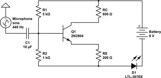
Take a look at the example of a DC restorer circuit (clamper circuit).

And the "2" diode together with the RC circuit (\$C_{15}R_7\$) is nothing more than a peak voltage detection circuit. And this voltage is sent to the input of a Over-Voltage Protector (OVP) circuit.
G36
- 13,642
- 1
- 18
- 33
-
Hello, in essence the "2" diode together with the RC circuit (C15 & R7) isn't a half wave rectifier? I made a simulation (image on the link). https://i.postimg.cc/9MjrmTs1/Screenshot-2023-07-11-004921.png – 2 X Jul 10 '23 at 21:52
-
1Yes, but in this case we use it as a peak voltage detector. http://www.learningaboutelectronics.com/Articles/Peak-detector-circuit.php – G36 Jul 11 '23 at 15:16