0

I'm making a doorbell and i've tested it on my breadboard where it works perfectly fine. However, when I transfer it to a soldered circuit I have some issues. The switching of the transistor is ok, and works with my reciever/transmitter circuit. But the transistor does not draw current from the 9 V battery attached at the collector. Instead it draws current from the Arduino board, just enough to turn on the amplifier circuit but not enough for any sound to play. I'm guessing it has something to do with my wiring or setup at the soldering board? There should be no conductivity issues between the soldering tho.

Any tips or recommendations are highly appreciated. I have attached a quick schematic and a picture of my horrible soldering job.

UPDATE1: I've included a picture of my wiring.

UPDATE2: And now also of the final schematic after all the kind suggestions:)

Final schematic

most orange: 5v from Arduino to reciever, orange: from arduino_11 to trans. base, purple: from reciever D2 to arduino_2, red: 9v+, green: 9v-, white: emitter to amp+, gray: arduino_gnd to amp-.
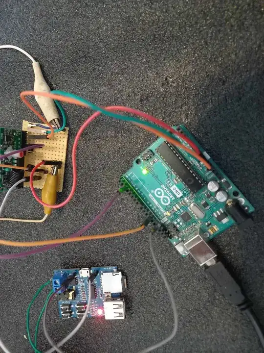
wiring

enter image description here

enter image description here

first schematic

  • Your schematic shows a NPN connected backwards and without bias resistor(s), fix that before anything else. – Lundin Jul 06 '23 at 13:25
  • I understand now, thanks! There should be a current limiting resistor at the base and the transistor should be switched around as Michal Podmanický has shown. And is it necessary for my circuit to add a base-emitter resistor to prevent a floating base as explained in: \\ Passerby (https://electronics.stackexchange.com/users/17178/passerby), What is the objective of a base-emitter resistor?, URL (version: 2016-02-03): https://electronics.stackexchange.com/q/215211 – Aleksander Lauridsen Jul 07 '23 at 07:51

2 Answers2

2

Seems the transistor is connected wrong.
Try to put speaker into collector path of 2n2222.
Btw, what kind of speaker is it? Is it 9V tolerant type?

schematic

simulate this circuit – Schematic created using CircuitLab

  • I tried to put the amplifier module into the collector path of 2n2222 and the other way around. It does not seem to do the trick. The amplifier module has a max current rating of 500 mA, and draws around 200-300 mA when it's working properly and playing audio. However no matter which way i add it in the transistor configuration it does not seems to draw enough current from the 9v battery. I've updated my post for clarification of how i wire it up. – Aleksander Lauridsen Jul 06 '23 at 10:10
0

No worries, it works as intended and first laid out. There was a loose connection between the ground to the 9V battery or something. I ended up hooking the ground to the reciever and the 9v battery up just next to each other and now it works.