4

I would like to know how to filter the pixel clock in order to reduce emitted radiations.
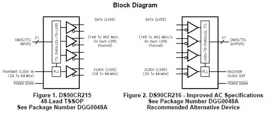
Block diagram

LCD controller and TFT LCD interface block diagram

The LCD controller is part of a motherboard. A board, connected at the other side of the FFC cable (15 cm), filters the signals on the TFT LCD side.

The used filters are EMIFIL chip ferrite beads (BLA2ABB121SN4 from Murata).

Investigation

EMC tests have been done on the machine that embeds these cards and the results showed that an unacceptable peak (~5dB greater than the limit) occurs at an harmonic of the pixel clock (~60MHz). This peak is generated when the 15 cm length cable is connected to the motherboard (regardless of the connexion of the other board nor the LCD).

A ferrite bead (Kitagawa SSC-40-12M) has been plugged on the FFC cable (15 cm length) but it didn't reduce this peak drastically.

Limitations

  • The ground of each board cannot be connected to the chassis.
  • The pixel clock frequency cannot be reduced (flickering occurs at lower frequencies).
  • The length of the FFC cables cannot be reduced.

Question

Should I use termination resistors on both sides in order to reduce eventual ringings? Or is there any other good practice to prevent this kind of radiations?

Edited - 2013-04-29

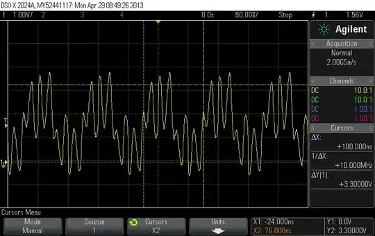
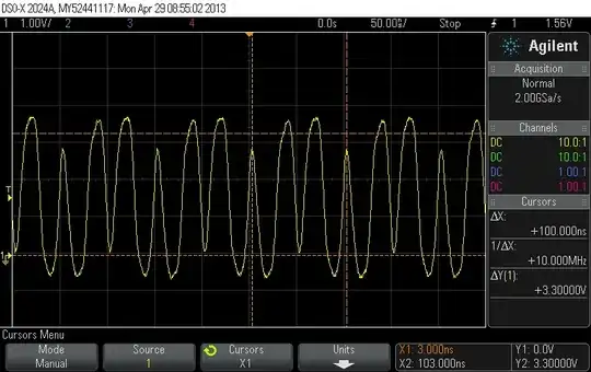
I measured the pixel clock frequency at the following places and it looks really horrible as you can see. Furthermore, its frequency should be 30MHz and it seems that it is only 10MHz. I suspect a bad line impedance matching. What's your feeling about this signal?

Measurement done on the LCD controller pin

enter image description here

Measurement done after the first EMI filter (on the LCD controller side of the FFC cable)

enter image description here

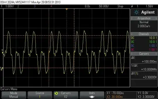
Measurement done on the LCD display side of the long FFC cable (before the second EMI filter)

enter image description here

Measurement done after the second EMI filter (just before the second FFC cable)

enter image description here

Honestly, I do not understand this waveform. It sounds like there are signal reflections or something like that. Any ideas?

johsey
  • 358
  • 1
  • 6
  • 12
  • How are you connecting your scope-ground when probing the clock? If you're using the normal ground clip-lead, that's where most of your garbage is coming from. – Connor Wolf May 29 '13 at 10:30
  • @ConnorWolf I'm using a 10:1 passive probe, 300MHz, 10MOhm//15pF with a short spring-loaded ground lead applied to the ground pad of a component in the nearest area. I measured the pixel clock on an evaluation board with the same LCD controller but without EMI filters and the signal is clean compared to this one. So the problem doesn't seem to come from the measuremet itself. – johsey May 30 '13 at 09:34
  • I know this is an old post, but did you ever resolve this? –  Oct 14 '15 at 16:47

3 Answers3

2

Experimentally wrap tinfoil round the cable, and earth it at the driving end. Or the chassis, but not both. If that works, you can find a better way of screening the cable.

Or a series termination at the driving end of the clock signal; this will somewhat slow up the clock edges; in other words reduce the harmonic content.

I have my doubts about this : if the clock is 30MHz and the peak is at 60MHz that's only the second harmonic. Which means either : the clock is a LONG way from being a square wave (duty cycle is far from 50%) or: the EMI is from other sources (perhaps the RGB data : does the emission go away with the screen black?) Some further information from these experiments and questions may help.

EDIT: If you can scrape up a spare wire in the connector, add a differential driver for the clock at the driving end (the LCD controller) and transmit the clock and its complement down adjacent wires. At the receiving end (the LCD) use a differential receiver to regenerate the clock. This has two advantages : first, the clock waveform will be more accurately preserved despite the cables and EMC filters, and second, the radiation from the two clock lines will cancel each other out, reducing your EMC emissions.

  • We already tried to wrap tinfoil round the cable and to connect it to the chassis, but it didn't solve the problem. What do you mean by "driving end of the clock signal"? Is it just before the connector on the LCD controller side or is it just before the LCD display connector? As you can see in the plots added to my post, the pixel clock is far from an ideal square wave. Could it be a bad impedance matching issue? – johsey Apr 29 '13 at 08:05
  • The first question about those waveforms is how you measured them. If you used a normal scope probe with its 4-6inch earth lead, try again with a VERY short earth connection; typically using the earth ring right next to the probe tip. In any case you may be right to worry about this waveform : as I suggested, it's a long way from a square wave. –  Apr 29 '13 at 09:20
  • I measured them with a 10:1 passive probe, 300MHz, 10MOhm//15pF and with a long ground lead. I did the same measurements with a short spring-loaded ground lead but the measured signal remains the same. I'll try to add a series termination resistor and verify if the signal is better. – johsey May 01 '13 at 07:30
1

You might consider serialization and deserialization: -

enter image description here

I can vouch for the family of chips from TI - I've used the simpler 10 channel : 1 channel serializer and deserializer and it does what it says on the tin. Why should this be considered? If you cannot reduce EMI, then going from 18 unbalanced connections to 4 balanced pairs is going to reduce EMI by an order of magnitude. Here is the pdf file to the devices.

These devices are specifically intended for LCD and other display technologies and can work up to 10 metres.

Andy aka
  • 434,556
  • 28
  • 351
  • 777
  • I will study this way if I cannot solve the radiations problems by improving the impedance matching and the filtering of the pixel clock line. – johsey Apr 29 '13 at 08:13
0

What is driving the FPC? For example, if the host processor is a FPGA, it is possible to reduce the current drive and slew rate on the I/O pins. For example, on the Xilinx Spartan 6 UCF, it is possible to set both the slew rate and the drive. Quoting the Xilinx white paper on signal integrity (which is a good read if you suspect these problems):

Another technique used in FPGAs is to control the output slew rates. If delay is not an issue, SLOW output attributes can be used to reduce crosstalk and bounce. If slew rate control is not possible, the drive strength should be programmed to a lower strength; for example, using LVTTL2 rather than LVTTL12 drivers. The resulting higher output resistance absorbs reflections and improves signal integrity. External resistors are not necessary through the use of certain SelectIO™ interface options.

http://www.xilinx.com/support/documentation/white_papers/wp323.pdf

For high frequency data, so long as your signal delays are fairly matched it is better to have slower slew rates (that is, more sloped edges) rather than idealized square-wave-ish signals, in order to reduce crosstalk (especially across a FPC, where adjacent signals tend to couple).

Edit: Ops, I didn't see that you have an ASIC controller. You can try using termination resistors. Another trick is that if you suspect that the ringing is causing crosstalk, you can use a wider FPC and have every other signal be ground for high frequency signals.

Zuofu
  • 4,168
  • 2
  • 21
  • 36
  • I will put termination resistors in the next prototype and see if the pixel clock waveform is better. Actually, the pixel clock signal is surrounded by GND lines. Since the FFC is already 50 lines wide, so unfortunately it will be hard to add one ground by high frequency signal. – johsey Apr 29 '13 at 08:11