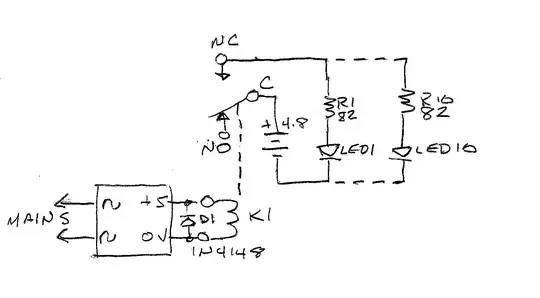
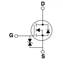
I'm using a ZVS driver to create a spark for a plasma speaker. The circuit above is the one I'm using for my project however I have run into some issues whihc I do not understand. First of all the circuit works when tested in LTspice but I had to use a startup to get the oscillation or else the MOSFETs did not switch.
However I made a prototype to compare the simulation results. When doing so I got no plasma spark, but when I disconnected the powersupply cables and held it on to the connection it made a spark. This made me think that the powersupply has a slow ramp up maybe. So to counter this I had a switch before the ZVS driver hoping this would solve the issue but it still does not work. All connections seem to be okay since a spark can be created. So I am confused how to solve this issue now. Perhaps there is some advanced circuit which I can add before the ZVS driver.
The components are not final, I was in a rush to have a design for a school project and from different ZVS drivers made the component choices.

